What is shear stress. bend
Flat (straight) bend- when the bending moment acts in a plane passing through one of the main central axes of inertia of the section, i.e. all forces lie in the plane of symmetry of the beam. Main hypotheses(assumptions): hypothesis of non-pressure of longitudinal fibers: fibers parallel to the axis of the beam experience tensile-compression deformation and do not exert pressure on each other in the transverse direction; hypothesis of flat sections: the section of a beam, which is flat before deformation, remains flat and normal to the curved axis of the beam after deformation. In the case of flat bending, in the general case, internal strength factors: longitudinal force N, transverse force Q and bending moment M. N>0 if the longitudinal force is tensile; at M>0, the fibers from above the beam are compressed, from below they are stretched. .
The layer in which there are no elongations is called neutral layer(axis, line). For N=0 and Q=0, we have the case clean bend. Normal stresses:  , is the radius of curvature of the neutral layer, y is the distance from some fiber to the neutral layer.
43) Eccentric tension and compression
Tension and compression
- normal voltage[Pa], 1Pa (pascal) \u003d 1 N / m 2, 
10 6 Pa \u003d 1 MPa (megapascal) \u003d 1 N / mm 2
N - longitudinal (normal) force [N] (newton); F - cross-sectional area [m 2]

- relative deformation [dimensionless value];
L - longitudinal deformation [m] (absolute elongation), L - rod length [m].
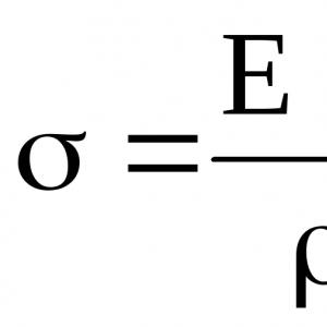
 -Hooke's law - = E
E - tensile modulus (modulus of elasticity of the 1st kind or Young's modulus) [MPa]. For steel E = 210 5 MPa = 210 6 kg / cm 2 (in the "old" system of units).
(the more E, the less extensible the material)
 ;
;
 - Hooke's law
EF - rod stiffness in tension (compression).
When the rod is stretched, it "thinns", its width - a decreases by transverse deformation - a.
 -relative transverse deformation.
 -Poisson's ratio [dimensionless value];
ranges from 0 (cork) to 0.5 (rubber); for steel 0.250.3.
If the longitudinal force and the cross section are not constant, then the elongation of the rod:

Tensile work:  , potential energy:
47. Mohr integral
A universal method for determining displacements (linear and rotation angles) is the Mohr method. A single generalized force is applied to the system at the point for which the generalized displacement is sought. If the deflection is determined, then the unit force is a dimensionless concentrated force, if the angle of rotation is determined, then it is a dimensionless unit moment. In the case of a spatial system, there are six components of internal forces. The generalized displacement is defined
48. Determination of stress under the combined action of bending and torsion
Bending with twist
The joint action of bending with torsion is the most common case of loading shafts. There are five components of internal forces: Q x , Q y , M x , M y , M z =M cr. When calculating, plots of bending M x , M y , and torque M cr moments are built and the dangerous section is determined. Resultant bending moment  . Max. normal and shear stresses at dangerous points (A, B):
  ,
,
 , (for circle: W=
  – axial moment of resistance ,
W p =
– axial moment of resistance ,
W p =  - polar moment of resistance of the section).
The main stresses at the most dangerous points (A and B):

The strength test is carried out according to one of the strength theories:
IV-th: Mohr's theory:
where m=[ p ]/[ c ] – admiss. e.g. tension / compression (for brittle materials - cast iron).
T  .k.W p =2W, we get:
The numerator is the reduced moment according to the accepted theory of strength. ;
II-nd: , with Poisson's coefficient =0.3;
III-I: 
or one formula:  , whence the moment of resistance:
  , shaft diameter:
  . The formulas are also suitable for calculating the annular section.
In the general case, during bending, any point of the beam is in a simplified plane stress state (Figure 1.14), along the edges of which both normal and shear stresses act

Solving the inverse problem for such a stressed state, one can find the position of the main area a o and the values of the main stresses σ 1, σ 3 according to the following dependencies
Let us analyze the stress state of dangerous points of the beam. To do this, consider the calculation scheme of a simple beam with diagrams of the transverse force Q and the bending moment M (Figure 1.15). Based on the height of the section of this beam, we construct diagrams of normal, tangential and principal stresses, taking into account dependencies (1.8) - (1.10).
In the general case, a complete check of the bending strength of a beam is performed according to the following three types of danger points .
Type I danger points: along the length of the beam are in sections where the maximum absolute value of the bending moment acts (section I-I), and along the height of the beam - in the extreme fibers of the section, where maximum normal stresses occur (points 1 and 5). At these points, a linear stress state occurs. The strength condition for type I points is as follows ( main strength condition)

Hazard points type II located along the length of the beam in sections with maximum transverse force (section II-II left and right), and along the height of the beam - at the level of the neutral line (point 3 left and right), where the maximum shear stress acts. At these points, a special case of a plane stress state arises - a pure shear. The strength condition has the following form:
Hazard points type III are located in the beam sections, where an unfavorable combination of large bending moment and transverse force occurs (section III-III left and right), and along the height of the beam - between the extreme fibers and the neutral line, where both normal and shear stresses are simultaneously large (points 2 and 4 left , right). At these points, a simplified plane stress state arises. The strength condition for type III points is written according to the theory of strength (for example, for a plastic material: according to theory III or IV).
If, as the calculations are performed, the strength according to one of the conditions is not met, then it is necessary to increase the dimensions of the beam section or increase the profile number according to the assortment tables.
The above analysis of the stress state of beams in bending makes it possible to rationally design elements of beam structures, taking into account the peculiarities of their loading. So, for example, for reinforced concrete structures, it is advisable to use steel reinforcement and place it along lines coinciding with the trajectory of the main tensile stresses.
With transverse bending in the cross section of the rod, not only a bending moment arises, but also a shearing force. Consequently, normal σ and shear stresses τ act in the cross section. According to the law of pairing of tangential stresses, the latter also arise in longitudinal sections, causing shifts of the fibers relative to each other and violating the hypothesis of flat sections adopted for pure bending. As a result flat sections bend under load. Scheme of deformations and force factors in the cross section of the rod during transverse bending. However in cases where the larger size of the section is several times smaller than the length of the rod, the shifts are small and the hypothesis of flat sections is extended to transverse bending. Therefore, normal stresses in transverse bending are also calculated using the pure bending formulas. Shear stresses in long rods (l>2h) are significantly less than normal ones. Therefore, they are not taken into account in the calculations of rods for bending, and the calculation for strength in transverse bending is carried out only for normal stresses, as in pure bending.
111 Complex types of rod deformations. (without one picture)
AT 
 In the general case, longitudinal and transverse loads can simultaneously act on the rod. If we assume a combination of oblique bending with axial tension or compression, then such loading leads to the appearance in the cross sections of the rod of bending moments M y and M z , transverse forces Q y and Q z and longitudinal force N. In the section AT cantilever rod will act the following force factors: M y =F z x; Mz=Fyx; Q z =F z ; Q y =F y ; N=F x . The normal stress caused by the tensile force F x is the same in all cross sections of the rod and is evenly distributed over the section. This stress is determined by the formula: σ p =F x /A, where A is the cross-sectional area of the rod. Applying the principle of independence of the action of forces (taking into account the formula), we obtain the following relation for determining the normal stress at an arbitrary point C: σ=N/A+M z z/J z +M z y/J z . Using this formula, it is possible to determine the maximum stress σ max in a given cross section σ max =N/A+M y /W y +M z /W z . The strength reliability condition for allowable stresses in this case has the form σ ma ≤ [σ]. Eccentric tension (compression). With eccentric tension (compression) of the rod, the resultant of external forces does not coincide with the beam axis, but is shifted relative to the x axis. This case of loading is similar in design terms to bending with tension. In an arbitrary cross section of the rod, internal force factors will act: M y =Fz B ; Mz B = Fy B ; N=F, where z B and y B are the coordinates of the force application point. The stresses at the points of the cross sections can be determined using the same formulas. Twisting with bending. Some structural elements operate under conditions of torsion and bending. For example, the gear shafts from the forces in the meshing of the teeth F 1 =F 2 transmit torque and bending moments. As a result, in cross section
normal and shear stresses will act: σ=M y z/J y ; τ=Tρ/J p , where M y and T are the bending and torque moments in the section, respectively. (PICTURE IS NOT INSERTED). The highest stresses acting at the peripheral points C and C R sections: σ max =M y /W y ; τ max =T/W p =T/(2W y). Based on the principal stresses, using one of the strength theories discussed above, the equivalent stress is determined. So, on the basis of energy theory: σ eq =√(σ 2 max +3 τ 2 max) .
In the general case, longitudinal and transverse loads can simultaneously act on the rod. If we assume a combination of oblique bending with axial tension or compression, then such loading leads to the appearance in the cross sections of the rod of bending moments M y and M z , transverse forces Q y and Q z and longitudinal force N. In the section AT cantilever rod will act the following force factors: M y =F z x; Mz=Fyx; Q z =F z ; Q y =F y ; N=F x . The normal stress caused by the tensile force F x is the same in all cross sections of the rod and is evenly distributed over the section. This stress is determined by the formula: σ p =F x /A, where A is the cross-sectional area of the rod. Applying the principle of independence of the action of forces (taking into account the formula), we obtain the following relation for determining the normal stress at an arbitrary point C: σ=N/A+M z z/J z +M z y/J z . Using this formula, it is possible to determine the maximum stress σ max in a given cross section σ max =N/A+M y /W y +M z /W z . The strength reliability condition for allowable stresses in this case has the form σ ma ≤ [σ]. Eccentric tension (compression). With eccentric tension (compression) of the rod, the resultant of external forces does not coincide with the beam axis, but is shifted relative to the x axis. This case of loading is similar in design terms to bending with tension. In an arbitrary cross section of the rod, internal force factors will act: M y =Fz B ; Mz B = Fy B ; N=F, where z B and y B are the coordinates of the force application point. The stresses at the points of the cross sections can be determined using the same formulas. Twisting with bending. Some structural elements operate under conditions of torsion and bending. For example, the gear shafts from the forces in the meshing of the teeth F 1 =F 2 transmit torque and bending moments. As a result, in cross section
normal and shear stresses will act: σ=M y z/J y ; τ=Tρ/J p , where M y and T are the bending and torque moments in the section, respectively. (PICTURE IS NOT INSERTED). The highest stresses acting at the peripheral points C and C R sections: σ max =M y /W y ; τ max =T/W p =T/(2W y). Based on the principal stresses, using one of the strength theories discussed above, the equivalent stress is determined. So, on the basis of energy theory: σ eq =√(σ 2 max +3 τ 2 max) .
116 Shear, internal forces and deformation.(Without internal force factors, the deformation is some kind of shit ).
FROM  displacement - a type of deformation when only a shearing force acts in the cross sections of the rod, and there are no other force factors. Shear corresponds to the action on the rod of two equal oppositely directed and infinitely close transverse forces,
causing a cut along a plane located between the forces (as when cutting bars, sheets, etc. with scissors). The cut is preceded by deformation - the distortion of the right angle between two mutually perpendicular lines. In this case, shear stresses τ arise on the faces of the selected element. The stress state in which only tangential stresses occur on the faces of the selected element is called pure shift. Value a called an absolute shift the angle by which the right angles of the element change is called relative shift, tgγ≈γ=a/h.
displacement - a type of deformation when only a shearing force acts in the cross sections of the rod, and there are no other force factors. Shear corresponds to the action on the rod of two equal oppositely directed and infinitely close transverse forces,
causing a cut along a plane located between the forces (as when cutting bars, sheets, etc. with scissors). The cut is preceded by deformation - the distortion of the right angle between two mutually perpendicular lines. In this case, shear stresses τ arise on the faces of the selected element. The stress state in which only tangential stresses occur on the faces of the selected element is called pure shift. Value a called an absolute shift the angle by which the right angles of the element change is called relative shift, tgγ≈γ=a/h.
Deformation. If a mesh is applied to the side surface of a round rod, then after twisting, one can detect : the generators of the cylinder circulate
in large pitch helical lines; sections are round and flat before deformation retain their shape, and after deformation; there is a rotation of one section relative to another at a certain angle, called the angle of twist; the distances between the cross sections practically do not change. Based on these observations, hypotheses are accepted that: sections that are flat before twisting remain flat after twisting; the cross-sectional radii remain straight during deformation. In accordance with this, the torsion of the rod can be represented as a result of shifts caused by the mutual rotation of the sections.
We have seen that in pure bending, only normal stresses arise in the cross sections of the rod. The corresponding internal forces are reduced to a bending moment in the section. In the case of transverse bending in the section of the rod, not only a bending moment arises, but also a transverse force. This force is the resultant of elementary distributed forces lying in the section plane (Fig. 4.23). Consequently, in this case, not only normal, but also shear stresses arise in the cross sections.

The occurrence of tangential stresses is accompanied by the appearance of angular deformations. Therefore, in addition to the basic displacements inherent in pure bending, each elementary area of the section receives some additional angular displacements due to shear. Shear stresses are unevenly distributed over the section, so angular displacements will also be unevenly distributed. This means that in case of transverse bending, in contrast to pure izpb a, the cross sections do not remain flat. On fig. 4.24 shows a typical picture of the curvature of the cross sections.


However, the distortion of the plane of cross sections does not noticeably affect the value of normal stresses. In particular, if the transverse force does not change along the length of the rod, formulas (4.6) and (4.8), derived for the case of pure bending, will give completely accurate results in the case of transverse bending. Indeed, when the curvature of all sections occurs in the same way (Fig. 4.25). Therefore, with mutual rotation of two adjacent sections, the elongation of the longitudinal fiber AB will be the same, regardless of whether the section remains flat or not.
With a transverse force varying along the rod axis, the pure bending formulas give some error for a. By a simple analysis, it can be shown that this error is of the order of magnitude compared to unity, where is the size of the cross section in the bending plane; - rod length. According to the definition given in § B2, a characteristic feature of a rod is that its cross-sectional dimensions are much less than its length. Consequently, the ratio is relatively small and the specified error turns out to be correspondingly small.
All of the above gives reason to accept the hypothesis of flat sections. We will further assume that the set of points that form the plane of the cross section before bending also forms a plane rotated in space after bending. This assumption is acceptable to the extent that the angular deformations 7 in the section can be considered significantly smaller than the angular displacements due to the change in curvature.
A feature of transverse bending is also the presence of normal stresses arising in the longitudinal sections of the beam, i.e. stresses between layers. These stresses arise only with a variable transverse force and are very small.
Thus, within the indicated assumptions, formulas (4.6) and (4.8), derived for determining normal stresses, are applicable not only for pure bending, but also for transverse bending. Equally applicable is formula (4.5), which gives the dependence of the curvature of the rod on the bending moment.
Now let us determine approximately the tangential stresses in transverse bending. The easiest way to calculate these stresses is through the paired shear stresses arising in the longitudinal sections of the rod. Let's select an element of length from the beam (Fig. 4.26, a). In case of transverse bending, the moments arising in the left and right sections of the element are not the same and differ in the longitudinal horizontal section drawn at a distance y from the neutral layer (Fig. 4.26, b), we divide the element into two parts and consider the equilibrium conditions of the upper part. The resultant of the normal forces in the left section within the shaded area is, obviously,

or, according to formula (4.6),


where, unlike y, denotes the current ordinate of the site (see Fig. 4.26, b). The resulting integral is the static moment about the x-axis of the part of the area located above the longitudinal section (above the level Let us denote this static moment by Then

In the right section, the normal force will be different:

The difference between these forces

must be balanced by tangential forces arising in the longitudinal section of the element (see Fig. 4.26, b and c).
As a first approximation, we assume that shear stresses are uniformly distributed over the width of the section. Then
![]()
The resulting formula is called the Zhuravsky formula, after the Russian scientist of the last century, who first conducted a general study of shear stresses in transverse bending.
Expression (4.12) allows one to calculate shear stresses arising in the longitudinal sections of the rod. The stresses formed in the cross sections of the rod are equal to them, as a pair. The dependence on y in the section is determined through the static moment 5. When approaching the upper edge of the section, the area of its shaded part (see Fig. 4.26, b) decreases to zero. Here, therefore, when approaching the lower edge, the shaded part covers the entire section. Since the axis is central, then here too. Therefore, the shear stresses, as follows from formula (4.12), at the upper and lower points of the section are equal to zero.

For a rectangular rod with sides and (Fig. 4.27, a) we have
Consequently,

and the diagram of tangential stresses along the height of the section is represented by a square parabola. The greatest stress occurs at
![]()
For a circular rod (Fig. 4.27, b), by a simple integration operation, you can find

Besides,
![]()
![]()
For a rod having a section in the form of a triangle with a base c and a height (Fig. 4.27, c),

The maximum stress occurs at a distance from the neutral axis:
![]()
The last two examples clearly demonstrate the approximate nature of the operations performed. This can be seen from the fact that in the cross section, shear stresses have components not only along the y axis, but also along the x axis. Indeed, let us assume, as was done above, that for points A located near the contour of the section (Fig. 4.28), the shear stress is directed along the y axis. Let us decompose the vector into two components - along the normal to the contour and along the tangent. According to the loading conditions, the outer surface of the rod is free from tangential forces. Therefore, there are no voltage pairs. Therefore, while the total shear stress near the contour is directed tangentially to the contour, and the assumption that it is directed along the y axis turns out to be incorrect. Thus, the presence of components along the x-axis is detected. To determine these components, one should resort to more complex methods than


reviewed earlier. Using the methods of the theory of elasticity, it can be shown that in most cases the components along the x-axis play a significantly smaller role than along the y-axis.
From the examples considered above, we can make a general conclusion that the zone of maximum shear stresses is located approximately in the middle part of the section height, and for non-thin-walled sections it has a value of the order
It is possible to compare the absolute values of the maximum normal and maximum shear stresses arising in the cross sections of the rod. For example, for a rectangular console (Fig. 4.29) we have

This means that the maximum shear stresses in the cross section are related to the maximum normal stresses approximately as the height of the section is related to the length of the rod, i.e. shear stresses are significantly less than normal. The specified estimate, with a few exceptions, is preserved for all non-thin-walled bars. As for thin-walled rods, this is a special issue.
Due to the smallness of τmax, the calculation for strength in transverse bending is performed only for normal stresses, as in pure bending. Shear stresses are not taken into account. This is all the more natural because at the points of the section that are farthest from the neutral line, i.e. in the most dangerous, shear stresses in the cross section are zero.
Considering the qualitative side of the phenomenon, it should be borne in mind that shear stresses in cross sections and paired stresses in longitudinal sections, despite their smallness, can in some cases significantly affect the assessment of the strength of the rod. For example, when transversely bending a short wooden beam, destruction is possible not along the cross section in the embedment, but shearing along the longitudinal plane close to the neutral layer, i.e. where shear stresses are maximum (Fig. 4.30).

Shear stresses in longitudinal sections are an expression of the existing connection between the layers of the rod during transverse bending. If this connection is broken in some layers, the nature of the bending of the rod changes. For example, in a rod made up of sheets (Fig. 4.31, a), each sheet bends independently in the absence of friction forces. The external force on the sheet is equal to and the greatest normal stress in the cross section of the sheet is equal to
In case of flat transverse bending, when the bending moment also acts in the sections of the beam M and shear force Q, not only normal  , but also shear stresses
  .
.
Normal stresses in transverse bending are calculated using the same formulas as in pure bending:

 ;
;  .(6.24)
P
Fig.6.11. flat bend
Shear stresses acting at the same distance at from the neutral axis, constant along the width of the beam;
Tangential stresses are everywhere parallel to the force Q.
Let us consider a cantilever beam under conditions of transverse bending under the action of a force R. Let's build diagrams of internal forces O y, and M z .
On distance x from the free end of the beam, we select an elementary section of the beam with a length dx and a width equal to the width of the beam b. Let us show the internal forces acting on the faces of the element: on the faces cd there is a transverse force Q y and bending moment M z, but on the verge ab- also transverse force Q y and bending moment M z +dM z(because Q y remains constant along the length of the beam, and the moment M z changes, Fig. 6.12). On distance at cut off part of the element from the neutral axis abcd, we will show the stresses acting on the faces of the obtained element mbcn, and consider its equilibrium. There are no stresses on the faces that are part of the outer surface of the beam. On the side faces of the element from the action of the bending moment M z, normal stresses arise:

 ;
(6.25)
;
(6.25)
 .
(6.26)
.
(6.26)
In addition, on these faces, from the action of a transverse force Q y, shear stresses arise  , the same stresses arise according to the law of pairing of tangential stresses on the upper face of the element.

Let's compose the balance equation of the element mbcn, projecting the resultant stresses under consideration onto the axis x:
 . (6.29)
The expression under the integral sign is the static moment of the side face of the element mbcn about the axis x, so we can write
 .
(6.30)
.
(6.30)
Given that, according to the differential dependencies of D. I. Zhuravsky, when bending,
 ,
(6.31)
,
(6.31)
expression for tangents stresses during transverse bending can be rewritten as follows ( Zhuravsky's formula)
 .
(6.32)
.
(6.32)
Let's analyze Zhuravsky's formula.
Q y is the transverse force in the considered section;
J z - axial moment of inertia of the section about the axis z;
b- section width in the place where shear stresses are determined;
 is the static moment about the z-axis of the part of the section located above (or below) the fiber where the shear stress is determined:
 , (6.33)
where  and F" - the coordinate of the center of gravity and the area of the considered part of the section, respectively.
6.6 Complete strength test. Dangerous sections and dangerous points
To check the bending strength, according to the external loads acting on the beam, plots of changes in internal forces along its length are built and the dangerous sections of the beam are determined, for each of which it is necessary to carry out a strength test.
With a full strength test, there will be at least three such sections (sometimes they coincide):
The section in which the bending moment M z reaches its maximum modulo value;
The section in which the transverse force Q y, reaches its maximum modulo value;
The section in which and the bending moment M z and shear force Q y reach sufficiently large values in modulus.
In each of the dangerous sections, it is necessary, having built diagrams of normal and shear stresses, to find the dangerous points of the section (strength check is carried out for each of them), which will also be at least three:
The point at which the normal stresses  , reach their maximum value, - that is, the point on the outer surface of the beam is the most distant from the neutral axis of the section;
The point at which shear stresses  reach their maximum value, - a point lying on the neutral axis of the section;
The point at which both normal stresses and shear stresses reach sufficiently large values (this check makes sense for sections such as a tee or I-beam, where the width of the section is not constant in height).