X-ray scattering. Absorption and scattering of X-rays
X-ray radiation refers to electromagnetic waves with a length of approximately 80 to 10 -5 nm. The longest-wave X-ray radiation is overlapped by short-wave ultraviolet radiation, and short-wave X-ray radiation is overlapped by long-wave γ-radiation. Based on the method of excitation, X-ray radiation is divided into bremsstrahlung and characteristic.
31.1. X-RAY TUBE DEVICE. Bremsstrahlung X-Ray
The most common source of X-ray radiation is an X-ray tube, which is a two-electrode vacuum device (Fig. 31.1). Heated cathode 1 emits electrons 4. Anode 2, often called an anticathode, has an inclined surface in order to direct the resulting X-ray radiation 3 at an angle to the tube axis. The anode is made of a highly heat-conducting material to remove heat generated by electron impacts. The anode surface is made of refractory materials that have a large atomic number in the periodic table, for example, tungsten. In some cases, the anode is specially cooled with water or oil.
For diagnostic tubes, the precision of the X-ray source is important, which can be achieved by focusing electrons in one place of the anticathode. Therefore, constructively it is necessary to take into account two opposing tasks: on the one hand, electrons must fall on one place of the anode, on the other hand, in order to prevent overheating, it is desirable to distribute electrons over different areas of the anode. One interesting technical solution is an X-ray tube with a rotating anode (Fig. 31.2).
As a result of the braking of an electron (or other charged particle) by the electrostatic field of the atomic nucleus and atomic electrons of the substance, an anticathode arises Bremsstrahlung X-ray radiation.
Its mechanism can be explained as follows. Associated with a moving electric charge is a magnetic field, the induction of which depends on the speed of the electron. When braking, the magnetic field decreases
induction and, in accordance with Maxwell's theory, an electromagnetic wave appears.
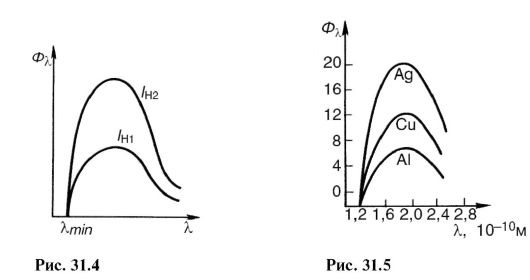
When electrons are decelerated, only part of the energy is used to create an x-ray photon, the other part is spent on heating the anode. Since the relationship between these parts is random, when a large number of electrons are decelerated, a continuous spectrum of X-ray radiation is formed. In this regard, bremsstrahlung is also called continuous radiation. In Fig. Figure 31.3 shows the dependence of the X-ray flux on the wavelength λ (spectra) at different voltages in the X-ray tube: U 1< U 2 < U 3 .
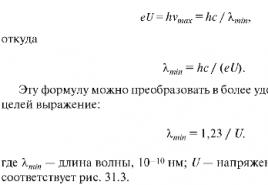
In each of the spectra, the shortest-wavelength bremsstrahlung is λ ηίη occurs when the energy acquired by an electron in an accelerating field is completely converted into photon energy:

Note that based on (31.2), one of the most accurate methods for experimentally determining Planck’s constant has been developed.
Short-wave X-rays are generally more penetrating than long-wave X-rays and are called tough, and long-wave - soft.
By increasing the voltage on the X-ray tube, the spectral composition of the radiation changes, as can be seen from Fig. 31.3 and formulas (31.3), and increase rigidity.
If you increase the filament temperature of the cathode, the emission of electrons and the current in the tube will increase. This will increase the number of X-ray photons emitted every second. Its spectral composition will not change. In Fig. Figure 31.4 shows the spectra of X-ray bremsstrahlung at the same voltage, but at different cathode heating currents: / n1< / н2 .
The X-ray flux is calculated using the formula:

Where U And I - voltage and current in the X-ray tube; Z- serial number of the atom of the anode substance; k- proportionality coefficient. Spectra obtained from different anticathodes at the same U and I H are shown in Fig. 31.5.
31.2. CHARACTERISTIC X-RAY RADIATION. ATOMIC X-RAY SPECTRA
By increasing the voltage on the X-ray tube, one can notice against the background of a continuous spectrum the appearance of a line spectrum, which corresponds to
characteristic x-ray radiation(Fig. 31.6). It arises due to the fact that accelerated electrons penetrate deep into the atom and knock out electrons from the inner layers. Electrons from the upper levels move to free places (Fig. 31.7), as a result, photons of characteristic radiation are emitted. As can be seen from the figure, characteristic X-ray radiation consists of series K, L, M etc., the name of which served to designate the electronic layers. Since the emission of the K-series frees up places in higher layers, lines of other series are also emitted at the same time.
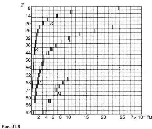
In contrast to optical spectra, the characteristic X-ray spectra of different atoms are of the same type. In Fig. Figure 31.8 shows the spectra of various elements. The uniformity of these spectra is due to the fact that the internal layers of different atoms are identical and differ only energetically, since the force action from the nucleus increases as the atomic number of the element increases. This circumstance leads to the fact that the characteristic spectra shift towards higher frequencies with increasing nuclear charge. This pattern is visible from Fig. 31.8 and is known as Moseley's law:

Where v- spectral line frequency; Z- atomic number of the emitting element; A And IN- permanent.
There is another difference between optical and x-ray spectra.
The characteristic X-ray spectrum of an atom does not depend on the chemical compound in which this atom is included. For example, the X-ray spectrum of the oxygen atom is the same for O, O 2 and H 2 O, while the optical spectra of these compounds are significantly different. This feature of the X-ray spectrum of the atom served as the basis for the name characteristic.
Characteristic radiation always occurs when there is free space in the inner layers of the atom, regardless of the reason that caused it. For example, characteristic radiation accompanies one of the types of radioactive decay (see 32.1), which consists in the capture of an electron from the inner layer by the nucleus.
31.3. INTERACTION OF X-RAY RADIATION WITH MATTER
The registration and use of X-ray radiation, as well as its impact on biological objects, are determined by the primary processes of interaction of the X-ray photon with the electrons of atoms and molecules of the substance.
Depending on the energy ratio hv photon and ionization energy 1 A and three main processes take place.
Coherent (classical) scattering
Scattering of long-wave X-rays occurs essentially without changing wavelength, and is called coherent. It occurs if the photon energy is less than the ionization energy: hv< A and.
Since in this case the energy of the X-ray photon and the atom does not change, coherent scattering in itself does not cause a biological effect. However, when creating protection against X-ray radiation, the possibility of changing the direction of the primary beam should be taken into account. This type of interaction is important for X-ray diffraction analysis (see 24.7).
Incoherent scattering (Compton effect)
In 1922 A.Kh. Compton, observing the scattering of hard X-rays, discovered a decrease in the penetrating power of the scattered beam compared to the incident beam. This meant that the wavelength of the scattered X-rays was longer than the incident X-rays. Scattering of X-rays with a change in wavelength is called incoherent nom, and the phenomenon itself - Compton effect. It occurs if the energy of the X-ray photon is greater than the ionization energy: hv > A and.
This phenomenon is due to the fact that when interacting with an atom, the energy hv photon is spent on the formation of a new scattered X-ray photon with energy hv", to remove an electron from an atom (ionization energy A and) and impart kinetic energy to the electron E to:
hv= hv" + A and + E k.(31.6)
1 Here, ionization energy refers to the energy required to remove internal electrons from an atom or molecule.
Since in many cases hv>> And and the Compton effect occurs on free electrons, then we can write approximately:
hv = hv"+ E K .(31.7)
It is significant that in this phenomenon (Fig. 31.9), along with secondary X-ray radiation (energy hv" photon) recoil electrons appear (kinetic energy E k electron). Atoms or molecules then become ions.
Photo effect
In the photoelectric effect, X-rays are absorbed by an atom, causing an electron to be ejected and the atom to be ionized (photoionization).
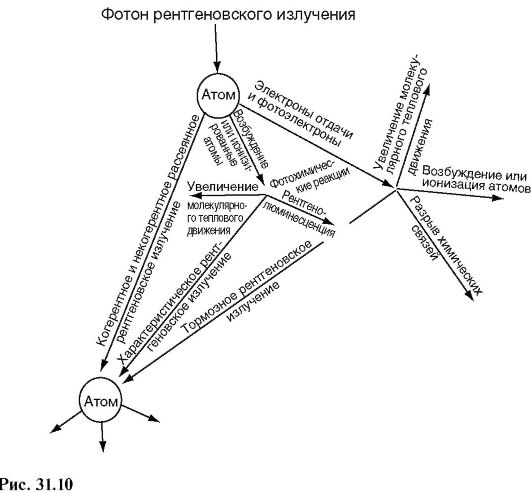
The three main interaction processes discussed above are primary, they lead to subsequent secondary, tertiary, etc. phenomena. For example, ionized atoms can emit a characteristic spectrum, excited atoms can become sources of visible light (x-ray luminescence), etc.
In Fig. 31.10 shows a diagram of possible processes that occur when X-ray radiation enters a substance. Several dozen processes similar to the one depicted can occur before the energy of the X-ray photon is converted into the energy of molecular thermal motion. As a result, changes in the molecular composition of the substance will occur.
The processes represented by the diagram in Fig. 31.10, form the basis of the phenomena observed when X-rays act on matter. Let's list some of them.
X-ray luminescence- glow of a number of substances under X-ray irradiation. This glow of platinum-synoxide barium allowed Roentgen to discover the rays. This phenomenon is used to create special luminous screens for the purpose of visual observation of X-ray radiation, sometimes to enhance the effect of X-rays on a photographic plate.
The chemical effects of X-ray radiation are known, for example the formation of hydrogen peroxide in water. A practically important example is the effect on a photographic plate, which allows such rays to be recorded.
The ionizing effect is manifested in an increase in electrical conductivity under the influence of X-rays. This property is used

in dosimetry to quantify the effects of this type of radiation.
As a result of many processes, the primary beam of X-ray radiation is weakened in accordance with the law (29.3). Let's write it in the form:
I = I 0 e-/", (31.8)
Where μ - linear attenuation coefficient. It can be represented as consisting of three terms corresponding to coherent scattering μ κ, incoherent μ ΗK and photoelectric effect μ f:
μ = μ k + μ hk + μ f. (31.9)
The intensity of X-ray radiation is attenuated in proportion to the number of atoms of the substance through which this flux passes. If you compress a substance along the axis X, for example, in b times, increasing by b since its density, then

31.4. PHYSICAL BASICS OF THE APPLICATION OF X-RAY RADIATION IN MEDICINE
One of the most important medical uses of X-rays is to illuminate internal organs for diagnostic purposes. (X-ray diagnostics).
For diagnostics, photons with an energy of about 60-120 keV are used. At this energy, the mass attenuation coefficient is mainly determined by the photoelectric effect. Its value is inversely proportional to the third power of the photon energy (proportional to λ 3), which shows the greater penetrating power of hard radiation, and proportional to the third power of the atomic number of the absorbing substance:

The significant difference in the absorption of X-ray radiation by different tissues allows one to see images of the internal organs of the human body in shadow projection.
X-ray diagnostics is used in two versions: fluoroscopy - the image is viewed on an X-ray luminescent screen, radiography - the image is recorded on photographic film.
If the organ being examined and surrounding tissues attenuate X-ray radiation approximately equally, then special contrast agents are used. For example, having filled the stomach and intestines with a porridge-like mass of barium sulfate, you can see their shadow image.
The brightness of the image on the screen and the exposure time on the film depend on the intensity of the x-ray radiation. If it is used for diagnostics, then the intensity cannot be high so as not to cause undesirable biological consequences. Therefore, there are a number of technical devices that improve images at low X-ray intensities. An example of such a device is electro-optical converters (see 27.8). During mass examination of the population, a variant of radiography is widely used - fluorography, in which an image from a large X-ray luminescent screen is recorded on a sensitive small-format film. When shooting, a high-aperture lens is used, and the finished images are examined using a special magnifier.

An interesting and promising option for radiography is a method called X-ray tomography, and its “machine version” - CT scan.
Let's consider this question.
A typical x-ray covers a large area of the body, with different organs and tissues obscuring each other. This can be avoided if you periodically move the X-ray tube together (Fig. 31.11) in antiphase RT and photographic film FP relative to the object About research. The body contains a number of inclusions that are opaque to x-rays; they are shown as circles in the figure. As can be seen, X-rays at any position of the X-ray tube (1, 2 etc.) go through
cutting the same point of the object, which is the center relative to which periodic movement occurs RT And Fp. This point, or rather a small opaque inclusion, is shown with a dark circle. His shadow image moves with FP, occupying sequential positions 1, 2 etc. The remaining inclusions in the body (bones, compactions, etc.) are created on FP some general background, since X-rays are not constantly obscured by them. By changing the position of the swing center, you can obtain a layer-by-layer X-ray image of the body. Hence the name - tomography(layered recording).
It is possible, using a thin beam of X-ray radiation, a screen (instead of Fp), consisting of semiconductor detectors of ionizing radiation (see 32.5), and a computer, process the shadow X-ray image during tomography. This modern version of tomography (computational or computed x-ray tomography) allows you to obtain layer-by-layer images of the body on a cathode ray tube screen or on paper with details less than 2 mm with a difference in x-ray absorption of up to 0.1%. This allows, for example, to distinguish between the gray and white matter of the brain and to see very small tumor formations.
EX = EX0 cos(wt – k0 z + j0) EY = EY0 cos(wt – k0 z + j0)
BX = BX0 cos(wt – k0 z + j0) BY = BY0 cos(wt – k0 z + j0)
where t is time, w is the frequency of electromagnetic radiation, k0 is the wave number, j0 is the initial phase. The wave number is the modulus of the wave vector and is inversely proportional to the wavelength k0 = 2π/l. The numerical value of the initial phase depends on the choice of the initial time t0=0. The quantities EX0, EY0, BX0, BY0 are the amplitudes of the corresponding components (3.16) of the electric and magnetic fields of the wave.
Thus, all components (3.16) of a plane electromagnetic wave are described by elementary harmonic functions of the form:
Y = A0 cos(wt – kz+ j0) (3.17)
Let us consider the scattering of a plane monochromatic X-ray wave on a set of atoms of the sample under study (on a molecule, a crystal of finite dimensions, etc.). The interaction of an electromagnetic wave with the electrons of atoms leads to the generation of secondary (scattered) electromagnetic waves. According to classical electrodynamics, scattering from an individual electron occurs at a solid angle of 4p and has significant anisotropy. If the primary X-ray radiation is not polarized, then the flux density of the scattered radiation of the wave is described by the following function
(3.18)where I0 is the primary radiation flux density, R is the distance from the scattering point to the place of registration of scattered radiation, q is the polar scattering angle, which is measured from the direction of the wave vector of the plane primary wave k0 (see Fig. 3.6). Parameter
» 2.818×10⁻⁶ nm(3.19)historically called the classical electron radius.
Fig.3.6. Polar scattering angle q of a plane primary wave on a small Cr sample under study.
A certain angle q defines a conical surface in space. The correlated movement of electrons within an atom complicates the anisotropy of scattered radiation. The amplitude of an X-ray wave scattered by an atom is expressed using a function of wavelength and polar angle f(q, l), which is called the atomic amplitude.
Thus, the angular distribution of the intensity of the X-ray wave scattered by an atom is expressed by the formula
 (3. 20)
and has axial symmetry relative to the direction of the wave vector of the primary wave k0. The square of the atomic amplitude f 2 is usually called the atomic factor.
As a rule, in experimental installations for X-ray diffraction and X-ray spectral studies, the detector of scattered X-rays is located at a distance R significantly greater than the dimensions of the scattering sample. In such cases, the input window of the detector cuts out an element from the surface of the constant phase of the scattered wave, which can be assumed to be flat with high accuracy.
Fig.3.8. Geometric diagram of X-ray scattering on atoms of sample 1 under Fraunhofer diffraction conditions.
2 – X-ray detector, k0 – wave vector of the primary X-ray wave, dashed arrows depict the fluxes of primary X-rays, dash-dotted ones – fluxes of scattered X-rays. Circles indicate atoms of the sample under study.
In addition, the distances between neighboring atoms of the irradiated sample are several orders of magnitude smaller than the diameter of the detector entrance window.
Consequently, in this registration geometry, the detector perceives a flow of plane waves scattered by individual atoms, and the wave vectors of all scattered waves can be assumed to be parallel with high accuracy.
The above features of X-ray scattering and their registration have historically been called Fraunhofer diffraction. This approximate description of the process of x-ray scattering on atomic structures allows one to calculate the diffraction pattern (angular distribution of the intensity of the scattered radiation) with high accuracy. The proof is that the Fraunhofer diffraction approximation underlies X-ray diffraction methods for studying matter, which make it possible to determine the parameters of unit cells of crystals, calculate the coordinates of atoms, establish the presence of various phases in a sample, determine the characteristics of crystal defects, etc.
Consider a small crystalline sample containing a finite number N of atoms with a certain chemical number.
Let us introduce a rectangular coordinate system. Its origin is compatible with the center of one of the atoms. The position of each atomic center (scattering center) is specified by three coordinates. xj, yj, zj, where j is the atomic number.
Let the sample under study be exposed to a plane primary X-ray wave with a wave vector k0 directed parallel to the Oz axis of the selected coordinate system. In this case, the primary wave is represented by a function of the form (3.17).
Scattering of X-rays by atoms can be either inelastic or elastic. Elastic scattering occurs without changing the wavelength of X-ray radiation. With inelastic scattering, the radiation wavelength increases, and the secondary waves are incoherent. Below, only elastic scattering of X-rays on atoms is considered.
Let us denote L as the distance from the origin to the detector. Let us assume that the Fraunhofer diffraction conditions are satisfied. This, in particular, means that the maximum distance between the atoms of the irradiated sample is several orders of magnitude smaller than the distance L. In this case, the sensitive element of the detector is exposed to plane waves with parallel wave vectors k. The moduli of all vectors are equal to the modulus of the wave vector k0 = 2π/l.
Each plane wave causes a harmonic oscillation with a frequency
(3.21)If the primary wave is satisfactorily approximated by a plane harmonic wave, then all secondary (scattered by atoms) waves are coherent. The phase difference of the scattered waves depends on the difference in the path of these waves.
Let us draw an auxiliary axis Or from the origin of coordinates to the location of the detector input window. Then each secondary propagating in the direction of this axis can be described by the function
y = A1 fcos(wt– kr+ j0) (3.22)
where the amplitude A1 depends on the amplitude of the primary wave A0, and the initial phase j0 is the same for all secondary waves.
A secondary wave emitted by an atom located at the origin of coordinates will create an oscillation of the sensitive element of the detector, described by the function
A1 f(q) cos(wt – kL+ j0) (3.23)
Other secondary waves will create oscillations with the same frequency (3.21), but differing from function (3.23) in phase shift, which in turn depends on the difference in the path of the secondary waves.
For a system of plane coherent monochromatic waves moving in a certain direction, the relative phase shift Dj is directly proportional to the path difference DL
Dj = k×DL(3.24)
where k is the wave number
k = 2π/l. (3.25)
To calculate the difference in the path of secondary waves (3.23), we first assume that the irradiated sample is a one-dimensional chain of atoms located along the Ox coordinate axis (see Fig. 3.9). The coordinates of the atoms are specified by the numbers xi, (j = 0, 1, …, N–1), where x0 = 0. The surface of the constant phase of the primary plane wave is parallel to the chain of atoms, and the wave vector k0 is perpendicular to it.
We will calculate a flat diffraction pattern, i.e. angular distribution of scattered radiation intensity in the plane shown in Fig. 3.9. In this case, the orientation of the detector location (in other words, the direction of the auxiliary axis Or) is specified by the scattering angle, which is measured from the Oz axis, i.e. on the direction of the wave vector k0 of the primary wave.
Fig.3.9. Geometric scheme of Fraunhofer diffraction in a given plane on a rectilinear chain of atoms
Without loss of generality of reasoning, we can assume that all atoms are located on the right Ox semi-axis. (except for the atom located at the center of coordinates).
Since the Fraunhofer diffraction conditions are satisfied, the wave vectors of all waves scattered by atoms arrive at the input window of the detector with parallel wave vectors k.
From Fig. 3.9 it follows that the wave emitted by an atom with coordinate xi travels a distance to the detector L – xisin(q). Consequently, the oscillation of the sensitive element of the detector caused by a secondary wave emitted by an atom with coordinate xi is described by the function
A1 f(q) cos(wt – k(L– xj sin(q)) + j0) (3.26)
The remaining scattered waves entering the window of the detector located in a given position have a similar appearance.
The value of the initial phase j0 is determined, in essence, by the moment when time begins to count. Nothing prevents you from choosing the value of j0 equal to –kL. Then the movement of the sensitive element of the detector will be represented by the sum
 (3.27)
This means that the difference in the paths of waves scattered by atoms with coordinates xi and x0 is –xisin(q), and the corresponding phase difference is equal to kxisin(q).
The frequency w of oscillations of electromagnetic waves in the X-ray range is very high. For X-rays with a wavelength l = Å, the frequency w in order of magnitude is ~1019 sec-1. Modern equipment cannot measure the instantaneous values of the electric and magnetic field strengths (1) with such rapid field changes, therefore all X-ray detectors record the average value of the square of the amplitude of electromagnetic oscillations.
At work at high voltages, as with radiography at ordinary voltages, it is necessary to use all known methods of combating scattered X-ray radiation.
Quantity scattered x-rays decreases with decreasing irradiation field, which is achieved by limiting the diameter of the working X-ray beam. With a decrease in the irradiation field, in turn, the resolution of the X-ray image improves, i.e., the minimum size of the detail detected by the eye decreases. To limit the diameter of the working X-ray beam, replaceable diaphragms or tubes are still far from being sufficiently used.
To reduce the amount scattered x-rays Compression should be used where possible. During compression, the thickness of the object under study decreases and, of course, there are fewer centers of formation of scattered X-ray radiation. For compression, special compression belts are used, which are included in X-ray diagnostic equipment, but they are not used often enough.
Amount of scattered radiation decreases with increasing distance between the X-ray tube and the film. By increasing this distance and corresponding aperture, a less divergent working beam of X-rays is obtained. As the distance between the X-ray tube and the film increases, it is necessary to reduce the irradiation field to the minimum possible size. In this case, the area under study should not be “cut off”.
To this end, in recent designs X-ray diagnostic devices have a pyramidal tube with a light centralizer. With its help, it is possible not only to limit the area being photographed to improve the quality of the X-ray image, but also to eliminate unnecessary irradiation of those parts of the human body that are not subject to radiography.
To reduce the amount scattered x-rays The part of the object being examined should be as close as possible to the X-ray film. This does not apply to direct magnification radiography. In radiography with direct image magnification, scattered observation practically does not reach the X-ray film.
Sandbags used for fixation the object under study should be located further from the cassette, since sand is a good medium for the formation of scattered X-ray radiation.
With radiography, produced on a table without the use of a screening grid, a sheet of leaded rubber of the largest possible size should be placed under the cassette or envelope with film.
For absorption scattered x-rays screening X-ray gratings are used, which absorb these rays as they exit the human body.
Mastering technology X-ray production at increased voltages on the X-ray tube, this is precisely the path that brings us closer to the ideal X-ray image, that is, one in which both bone and soft tissue are clearly visible in detail.
DIFFUSE SCATTERING OF X-RAYS- scattering of X-rays by matter in directions for which it is not carried out Bragg - Wolf condition.
In an ideal crystal, elastic scattering of waves by atoms located at periodic nodes. lattice, as a result, occurs only at a certain point. directions vector Q, coinciding with the directions of the reciprocal lattice vectors G: Q= k 2 -k 1 where k 1 and k 2 - wave vectors of the incident and scattered waves, respectively. The scattering intensity distribution in reciprocal lattice space is a set of d-shaped Laue-Bragg peaks at reciprocal lattice sites. Displacements of atoms from lattice sites disrupt the periodicity of the crystal, and interference. the picture is changing. In this case, in the scattering intensity distribution, along with the maxima (which remain if an averaged periodic lattice can be identified in a distorted crystal), a smooth component appears I 1 (Q), corresponding to D. r. R. l. on crystal imperfections.
Along with elastic scattering, D. r. R. l. may be due to inelastic processes accompanied by excitation of the electronic subsystem of the crystal, i.e., Compton scattering (see Compton effect) and scattering with plasma excitation (see. Solid state plasma). Using calculations or special experiments, these components can be excluded by highlighting D. r. R. l. on crystal imperfections. In amorphous, liquid and gaseous substances, where there is no long-range order, scattering is only diffuse.
Intensity distribution I 1 (Q) D. R. R. l. crystal in a wide range of values Q, corresponding to the entire unit cell of the reciprocal lattice or several cells, contains detailed information about the characteristics of the crystal and its imperfections. Experimentally I 1 (Q) can be obtained using a method using monochromatic. X-ray and allows you to rotate the crystal around different axes and change the directions of wave vectors k 1 , k 2, varying, i.e., Q over a wide range of values. Less detailed information can be obtained Debye - Scherrer method or Laue method.
In a perfect crystal D.r.r.l. caused only by thermal displacements and zero oscillations atoms of the lattice and can be associated with the processes of emission and absorption of one or more. . For small Q basic Single-phonon scattering plays a role, in which only phonons with q =Q-G, Where G-reciprocal lattice vector closest to Q. The intensity of such scattering I 1T ( Q) in the case of monatomic ideal crystals is determined by the f-loy
Where N- number of elementary cells of the crystal, f-structural amplitude, - Debye-Waller factor, t- atomic mass,
-frequencies and . phonon vectors j th branch with wave vector q. At small q frequency, i.e., when approaching the nodes of the reciprocal lattice, it increases as 1/ q 2. Defining for vectors q, parallel or perpendicular to the directions , , in cubic crystals, where the oscillation frequencies for these directions are uniquely determined by considerations.
In nonideal crystals, defects of finite sizes lead to a weakening of the intensities of correct reflections I 0 (Q)and to D.r.r.l. I 1 (Q) to static displacements and changes in structural amplitudes caused by defects ( s- cell number near the defect, - type or orientation of the defect). In slightly distorted crystals with a low concentration of defects (the number of defects in the crystal) and ![]() intensity D.r.r.l.
intensity D.r.r.l.
where and are the Fourier components.
Displacements decrease with distance r from defect as 1/ r 2, as a result of which at small q and near reciprocal lattice nodes I 1 (Q)increases as 1/ q 2. Angle addiction I 1 (Q) is qualitatively different for defects of different types and symmetries, and the value I 1 (Q) is determined by the amount of distortion around the defect. Distribution study I 1 (Q) in crystals containing point defects (for example, interstitial atoms and vacancies in irradiated materials, impurity atoms in weak solid solutions), makes it possible to obtain detailed information about the type of defects, their symmetry, position in the lattice, configuration of atoms forming the defect, tensors dipoles of forces with which defects act on the crystal.
When combining point defects into groups, the intensity I 1 in the field of small q increases strongly, but turns out to be concentrated in relatively small regions of reciprocal lattice space near its nodes, and at ( R0- size of the defect) decreases quickly.
Study of areas of intensive D. r. R. l. makes it possible to study the size, shape and other characteristics of particles of the second phase in aging solutions. loops of small radius in irradiated or deformed. materials.
When means. concentrations of large defects, the crystal is strongly distorted not only locally near the defects, but also as a whole, so that in most of its volume. As a result, the Debye-Waller factor and the intensity of correct reflections I 0 decrease exponentially, and the distribution I 1 (Q) is qualitatively rearranged, forming broadened peaks slightly displaced from the reciprocal lattice nodes, the width of which depends on the size and concentration of defects. Experimentally, they are perceived as broadened Bragg peaks (quasi-lines on the Debye diagram), and in some cases diffraction patterns are observed. doublets consisting of pairs of peaks I 0 and I 1. These effects appear in aging alloys and irradiated materials.
In concentrated solutions, single-component ordered crystals, ferroelectrics, non-ideality is not due to separate factors. defects, and fluctuations. inhomogeneities of concentration and internal parameters and I 1 (Q) can be conveniently considered as scattering by q th. fluctuation wave of these parameters ( q=Q-G). For example, in binary solutions A - B with one atom per cell, neglecting static scattering. displacements
Where f A and f B-atomic scattering factors of atoms A and B, With- concentration - correlation parameters, - probability of substitution of a pair of nodes separated by a lattice vector A, atoms A. Having determined I 1 (Q) in the entire cell of the reciprocal lattice and by performing the Fourier transform f-tions can be found for decomp. coordination spheres Static scattering biases are excluded based on intensity data I 1 (Q) in several reciprocal lattice cells. Distributions I 1 (Q) can also be used directly. determination of solution ordering energies for different A in the model of pair interaction and its thermodynamic. characteristics. Features of D.r.r.l. metallic solutions made it possible to develop diffraction. research method truss-surface alloys
In systems located in states close to the points of phase transition of the 2nd order and critical. points on the decay curves, fluctuations increase sharply and become large-scale. They cause intense criticism. D. r. R. l. in the vicinity of reciprocal lattice nodes. His study allows one to obtain important information about the features of phase transitions and the behavior of thermodynamics. values near transition points.
Diffuse scattering of thermal neutrons by static. heterogeneities similar to D. r. R. l. and is described by similar phrases. The study of neutron scattering makes it possible to study also dynamic. characteristics of atomic vibrations and fluctuations. heterogeneities (see Inelastic neutron scattering).
Lit.: James R., Optical principles of X-ray diffraction, trans. from English, M., 1950; Iveronova V.I., Revkevich G.P., Theory of X-ray scattering, 2nd ed., M., 1978; Iveronova V.I., Katsnelson A.A., Short-range order in solid solutions, M., 1977; Cowley J., Physics of Diffraction, trans. from English, M., 1979; Krivoglaz M A., Diffraction of X-rays and neutrons in nonideal crystals, K., 1983; by him, Diffuse scattering of X-rays and neutrons on fluctuation inhomogeneities in nonideal crystals, K., 1984.
M. A. Krivoglaz.
Unlike many speculations about the structure of the atom that were widespread at that time, Thomson's model was based on physical facts that not only justified the model, but also gave certain indications of the number of corpuscles in an atom. The first such fact is the scattering of X-rays, or, as Thomson said, the occurrence of secondary X-rays. Thomson views X-rays as electromagnetic pulsations. When such pulsations fall on atoms containing electrons, the electrons, coming into accelerated motion, emit as described by the Larmor formula. The amount of energy emitted per unit time by electrons located in a unit volume will be
where N is the number of electrons (corpuscles) per unit volume. On the other hand, electron acceleration
![]()
where E p is the field strength of the primary radiation. Consequently, the intensity of the scattered radiation

Since the intensity of incident radiation according to Poynting’s theorem is equal to
![]()
then the ratio of scattered energy to primary

Charles Glover Barcla, who received the Nobel Prize in 1917 for the discovery of characteristic X-rays, was in 1899-1902. as a "research student" (graduate student) with Thomson at Cambridge, and here he became interested in X-rays. In 1902, he was a teacher at University College in Liverpool, and here in 1904, while studying secondary X-ray radiation, he discovered its polarization, which was quite consistent with Thomson's theoretical predictions. In the final experiment of 1906, Barkla caused the primary beam to be scattered by carbon atoms. The scattered beam fell perpendicular to the primary beam and was again scattered by carbon. This tertiary beam was completely polarized.
While studying the scattering of X-rays from light atoms, Barcla in 1904 found that the nature of the secondary rays was the same as the primary ones. For the ratio of the intensity of the secondary radiation to the primary one, he found a value independent of the primary radiation and proportional to the density of the substance:
From Thomson's formula


But density = n A / L, where A is the atomic weight of the atom, n is the number of atoms in 1 cm 3, L is Avogadro's number. Hence,

If we put the number of corpuscles in an atom equal to Z, then N = nZ and
![]()

If we substitute the values of e, m, L to the right side of this expression, we will find K. In 1906, when the numbers e and m were not precisely known, Thomson found from Barkle’s measurements for air that Z = A, i.e. the number of corpuscles in an atom is equal to the atomic weight. The value of K obtained for light atoms by Barkle back in 1904 was K = 0.2. But in 1911, Barkla, using Bucherer’s updated data for e / m, the values of e and L obtained Rutherford And Geiger, received K = 0.4, and therefore, Z = 1/2. As it turned out a little later, this relationship holds well in the region of light nuclei (with the exception of hydrogen).
Thomson's theory helped clarify a number of issues, but left even more questions unresolved. The decisive blow to this model was dealt by Rutherford's experiments in 1911, which will be discussed later.
A similar ring model of the atom was proposed in 1903 by a Japanese physicist Nagaoka. He suggested that at the center of the atom there is a positive charge, around which rings of electrons revolve, like the rings of Saturn. He managed to calculate the periods of oscillations performed by electrons with minor displacements in their orbits. The frequencies obtained in this way more or less approximately described the spectral lines of some elements *.
* (It should also be noted that the planetary model of the atom was proposed in 1901. J. Perrin. He mentioned this attempt in his Nobel lecture, given on December 11, 1926.)
On September 25, 1905, at the 77th Congress of German Naturalists and Doctors, V. Wien made a report on electrons. In this report, by the way, he said the following: “The explanation of spectral lines also poses a great difficulty for electronic theory. Since each element corresponds to a certain grouping of spectral lines that it emits while in a state of luminescence, each atom must represent an unchanging system. It would be easiest to think of the atom as a planetary system consisting of a positively charged center around which negative electrons revolve, like planets. But such a system cannot be unchanged due to the energy emitted by the electrons. Therefore, we are forced to turn to a system in which the electrons are in relative rest or have negligible speeds - a concept that contains a lot of doubtful things."
These doubts increased even more as new mysterious properties of radiation and atoms were discovered.