Creation of unfolded bodies of revolution. Creation of a flat pattern of a cone Flat pattern of a cone with an offset center
There are 2 ways to construct a flat pattern of a cone:
- Divide the base of the cone into 12 parts (we enter the correct polyhedron - a pyramid). You can divide the base of the cone into more or less parts, because the smaller the chord, the more accurate the construction of the sweep of the cone. Then transfer the chords to the arc of the circular sector.
- Constructing a sweep of a cone, according to the formula that determines the angle of the circular sector.
Since we need to apply the intersection lines of the cone and the cylinder to the sweep of the cone, we still have to divide the base of the cone into 12 parts and inscribe the pyramid, so we will immediately go along 1 path for constructing the sweep of the cone.
Algorithm for constructing a sweep of a cone
- We divide the base of the cone into 12 equal parts (we enter the correct pyramid).
- We build the lateral surface of the cone, which is a circular sector. The radius of the circular sector of the cone is equal to the length of the generatrix of the cone, and the length of the arc of the sector is equal to the circumference of the base of the cone. We transfer 12 chords to the arc of the sector, which will determine its length, as well as the angle of the circular sector.
- Attach the base of the cone to any point of the arc of the sector.
- We draw generators through the characteristic points of intersection of the cone and the cylinder.
- Find the actual size of the generators.
- We build these generators on a flat sweep of the cone.
- We connect the characteristic points of intersection of the cone and the cylinder on the flat pattern.
More details in the video tutorial on descriptive geometry in AutoCAD.
During the construction of the flat pattern of the cone, we will use the Array in AutoCAD - Circular array and array along the path. I recommend viewing these AutoCAD video tutorials. At the time of this writing, the AutoCAD 2D video course contains a classic way of constructing a circular array and an interactive one when constructing an array along a path.
A flat surface of a cone is a flat figure obtained by aligning the side surface and the base of the cone with a certain plane.
Scanning options:
Flattened circular cone
The sweep of the lateral surface of a straight circular cone is a circular sector, the radius of which is equal to the length of the generatrix of the conical surface l, and the central angle φ is determined by the formula φ = 360 * R / l, where R is the radius of the circumference of the base of the cone.
In a number of problems of descriptive geometry, the preferred solution is the approximation (replacement) of a cone with a pyramid inscribed in it and the construction of an approximate sweep, on which it is convenient to draw lines lying on the conical surface.
Construction Algorithm
- We fit a polygonal pyramid into the conical surface. The more side faces the inscribed pyramid has, the more accurate the correspondence between the actual and the approximate scan.
- We build a development of the side surface of the pyramid using the triangles method. We connect the points belonging to the base of the cone with a smooth curve.
Example
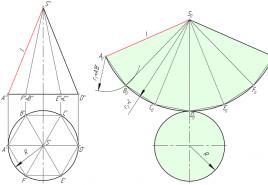
In the figure below, a regular hexagonal pyramid SABCDEF is inscribed in a straight circular cone, and an approximate sweep of its lateral surface consists of six isosceles triangles - the faces of the pyramid.

Consider a triangle S 0 A 0 B 0. The lengths of its sides S 0 A 0 and S 0 B 0 are equal to the generatrix l of the conical surface. The value A 0 B 0 corresponds to the length A'B '. To construct a triangle S 0 A 0 B 0 in an arbitrary place of the drawing, set aside the segment S 0 A 0 = l, after which from points S 0 and A 0 we draw circles with a radius S 0 B 0 = l and A 0 B 0 = A'B ' respectively. We connect the point of intersection of the circles B 0 with the points A 0 and S 0.
The faces S 0 B 0 C 0, S 0 C 0 D 0, S 0 D 0 E 0, S 0 E 0 F 0, S 0 F 0 A 0 of the SABCDEF pyramids are constructed similarly to the triangle S 0 A 0 B 0.
We connect the points A, B, C, D, E and F lying at the base of the cone with a smooth curve - an arc of a circle whose radius is equal to l.
Oblique taper sweep
Let us consider the procedure for constructing a sweep of the lateral surface of an inclined cone by the approximation (approximation) method.

Algorithm
- We inscribe hexagon 123456 into the circle of the base of the cone. Connect points 1, 2, 3, 4, 5 and 6 with vertex S.
- We determine the natural values of the edges of the pyramid using the method of rotation around the projecting line: in the example, the i-axis is used, perpendicular to the horizontal plane of the projections and passing through the vertex S.
So, as a result of the rotation of the rib S5, its new horizontal projection S'5 '' 1 takes a position at which it is parallel to the frontal plane π 2. Accordingly, S''5''''1 is the actual size S5. - We build a development of the side surface of the pyramid S123456, consisting of six triangles: S 0 1 0 6 0, S 0 6 0 5 0, S 0 5 0 4 0, S 0 4 0 3 0, S 0 3 0 2 0, S 0 2 0 1 0. Each triangle is constructed on three sides. For example, for △ S 0 1 0 6 0 the length is S 0 1 0 = S''1 ’’ 0, S 0 6 0 = S''6 ’’ 1, 1 0 6 0 = 1'6 ’.
The degree to which the approximate scan corresponds to the actual one depends on the number of faces of the inscribed pyramid. The number of faces is selected based on the ease of reading the drawing, the requirements for its accuracy, the presence of characteristic points and lines that need to be transferred to the scan.
Transferring a line from the surface of a cone to a flat pattern
Line n, lying on the surface of the cone, is formed as a result of its intersection with a certain plane (figure below). Consider the algorithm for constructing the line n on the sweep.

Algorithm
- Find the projections of points A, B and C at which line n intersects the edges of the pyramid S123456 inscribed in the cone.
- Determine the actual size of the segments SA, SB, SC by rotating around the projecting line. In this example, SA = S''A '', SB = S''B''''1, SC = S''C''''1.
- We find the position of the points A 0, B 0, C 0 on the corresponding edges of the pyramid, postponing on the sweep the segments S 0 A 0 = S `` A '', S 0 B 0 = S `` B '' 1, S 0 C 0 = S``C '' 1.
- Connect the points A 0, B 0, C 0 with a smooth line.
Truncated cone flat pattern
The method described below for constructing a sweep of a straight circular truncated cone is based on the principle of similarity.

It is necessary to build a flat pattern of surfaces and transfer the line of intersection of surfaces to the flat pattern. This problem is based on surfaces ( cone and cylinder) with their line of intersection given in previous problem 8.
To solve such problems in descriptive geometry, you need to know:
- the procedure and methods for constructing unfolded surfaces;
- mutual correspondence between the surface and its unfolding;
- special cases of building sweeps.
Decision proceduresproblems
1.
Note that a sweep is a figure obtained in
as a result of cutting the surface along some generatrix and gradually unbending it until it is completely aligned with the plane. Hence the sweep of a straight circular cone - a sector with a radius equal to the length of the generatrix and a base equal to the circumference of the base of the cone. All sweeps are built only from natural values.
Figure 9.1
- the circumference of the base of the cone, expressed in natural value, we divide by a number of shares: in our case - 10, the accuracy of building the sweep depends on the number of shares ( fig. 9.1.a);
- we postpone the received shares, replacing them with chords, along the length
an arc drawn with a radius equal to the length of the generatrix of the cone l = | Sb |. We connect the beginning and end of the counting of the shares to the top of the sector - this will be the sweep of the lateral surface of the cone.
Second way:
- we build a sector with a radius equal to the length of the generatrix of the cone.
Note that in both the first and second cases, the extreme right or left generators of the cone l = | Sb | are taken as the radius, since they are expressed in natural size;
- at the top of the sector, we postpone the angle a, determined by the formula:

Figure 9.2
where r- the value of the radius of the base of the cone;
l- the length of the generatrix of the cone;
360 - constant value converted to degrees.
To the unfolded sector, we build the base of the cone of radius r.
2.
According to the conditions of the problem, it is required to move the intersection line
surfaces of the cone and cylinder for a scan. To do this, we use the properties of one-to-one between the surface and its flat pattern, in particular, note that each point on the surface corresponds to a point on the flat pattern and each line on the surface corresponds to a line on the flat pattern.
This implies the sequence of transferring points and lines
from the surface to the sweep.

Figure 9.3
For sweeping the cone. Let us agree that the cut of the surface of the cone is made along the generatrix S’
a’
... Then the points 1, 2, 3,…6
will lie on circles (arcs on the sweep) with radii respectively equal to the distances taken along the generatrix S’
A’
from the top S’
to the corresponding secant plane with points 1’
, 2’, 3’…6’ -|
S1|, |
S2|, |
S3|….|
S6 | (Figure 9.1.b).
The position of the points on these arcs is determined by the distance taken from the horizontal projection from the generatrix Sa, along the chord to the corresponding point, for example, to the point c, ac = 35 mm ( fig. 9.1.a). If the distance along the chord and the arc is very different, then to reduce the error, you can divide a larger number of fractions and put them on the corresponding sweep arcs. In this way, any points are transferred from the surface to its flat pattern. The resulting points will be connected by a smooth curve along the pattern ( Figure 9.3).
To unroll the cylinder.
A cylinder sweep is a rectangle with a height equal to the generatrix height and a length equal to the circumference of the cylinder base. Thus, to build a flat pattern of a straight circular cylinder, it is necessary to construct a rectangle with a height equal to the height of the cylinder, in our case 100mm, and a length equal to the circumference of the base of the cylinder, determined by the known formulas: C=2 R= 220mm, or by dividing the circumference of the base into a series of shares, as indicated above. Attach the base of the cylinder to the upper and lower parts of the resulting scan.
Let us agree that the cut is made along the generatrix AA 1 (A’ A’ 1 ; AA1) ... Note that the cut should be made along the characteristic (control) points for a more convenient construction. Considering that the length of the sweep is the circumference of the base of the cylinder C, from point A’= A’ 1 section of the frontal projection, we take the distance along the chord (if the distance is large, then it must be divided into shares) to the point B’ (in our example - 17mm) and put it on the sweep (along the length of the base of the cylinder) from point A. From the obtained point B, draw a perpendicular (generatrix of the cylinder). Dot 1 should be on this perpendicular) at a distance from the base taken from the horizontal projection to the point. In our case, the point 1 lies on the axis of symmetry of the sweep at a distance 100/2 = 50mm (Figure 9.4).

Figure 9.4
And we do this to find all other points on the sweep.
We emphasize that the distance along the length of the sweep for determining the position of the points is taken from the frontal projection, and the distance along the height - from the horizontal, which corresponds to their natural values. We connect the resulting points with a smooth curve along the pattern ( Figure 9.4).
In the variants of the problems, when the intersection line splits into several branches, which corresponds to the complete intersection of surfaces, the methods of constructing (transferring) the intersection line to the flat pattern are similar to those described above.
Section: Descriptive Geometry /We take the perpendiculars to each segment, on them we lay down the real values of the generatrices of the cylinder, taken from the frontal projection. Connecting the obtained points together, we get a curve.
To obtain a full sweep, add a circle (base) and the actual size of the section (ellipse) to the sweep of the side surface, built along its major and minor axes or by points.
5.3.4. Creation of a flattened cone flat pattern
V In a particular case, the sweep of a cone is a flat figure consisting of a circular sector and a circle (the base of the cone).
V In the general case, the unfolding of the surface is carried out according to the principle of unfolding a polyhedral pyramid (that is, by the method of triangles) inscribed in a conical surface. The greater the number of faces of the pyramid inscribed in the conical surface, the less the difference between the actual and approximate sweeps of the conical surface will be.
The construction of the sweep of the cone begins with drawing from the point S 0 an arc of a circle with a radius equal to the length of the generatrix of the cone. On this arc, 12 parts of the circumference of the base of the cone are laid and the resulting points are connected to the top. An example of an image of a full scan of a truncated cone is shown in Fig. 5.7.

Lecture 6 (beginning)
MUTUAL CROSSING OF SURFACES. METHODS FOR CONSTRUCTING MUTUAL CROSSING SURFACES.
METHOD OF AUXILIARY SECTIONAL PLANES AND SPECIAL CASES
6.1. Mutual intersection of surfaces
Intersecting with each other, the surfaces of the bodies form various broken or curved lines, which are called lines of mutual intersection.
To draw lines of intersection of two surfaces, you need to find points that simultaneously belong to two specified surfaces.
When one of the surfaces completely penetrates the other, there are 2 separate intersection lines, called branches. In the case of a cut-in, when one surface partially enters the other, the line of intersection of the surfaces will be one.
6.2. Intersection of faceted surfaces
The intersection line of two polyhedra is a closed spatial polyline. Its links are the lines of intersection of the faces of one polyhedron with the faces of another, and the vertices are the points of intersection of the edges of one polyhedron with the faces of another. Thus, to construct a line of intersection of two polyhedra, you need to solve the problem either on the intersection of two planes (facet method), or on the intersection of a straight line with a plane (edge method). In practice, both methods are usually used in combination.
Intersection of a pyramid with a prism. Consider the case of intersection
of a pyramid with a prism, the lateral surface of which is projected by π3 onto the outline bases (quadrangle). We begin construction with a profile projection. When drawing points, we will use the edge method, that is, when the edges of the vertical pyramid intersect the edges of the horizontal prism (Fig. 6.1).

Analysis of the problem statement shows that the line of intersection of the pyramid and the prism splits into 2 branches, one of the branches is a flat polygon, points 1, 2, 3, 4 (points of intersection of the edges of the pyramid with the face of the prism). Their horizontal, frontal and profile projections are located on the projections of the corresponding edges and are determined by the communication lines. Similarly, points 5, 6, 7 and 8 can be found belonging to another branch. Points 9, 10, 11, 12 are determined from the condition that the upper and lower edges of the prism are parallel to each other, that is, 1 "2" is parallel to 5 "10", etc.
You can use the construction clipping planes method. The construction plane intersects both surfaces along the broken lines. The mutual intersection of these lines gives us the points belonging to the desired intersection line. We select α "" "and β" "" as auxiliary planes. Using the plane α "" "
we find the projections of points 1 ", 2", 3 ", 4", and the planes β "" "- points 5", 6 ", 9", 10 ", 11", 12 ". Points 7 and 8 are determined as in the previous method ...
6.3. Intersection of faceted surfaces
With surfaces of revolution
Most of the technical details and objects are composed of a combination of various geometric bodies. Intersecting with each other,
![]()
the surfaces of these bodies form various straight or curved lines, which are called lines of mutual intersection.
To build a line of intersection of two surfaces, you need to find points that would simultaneously belong to two surfaces.
When a polyhedron intersects with a surface of revolution, a spatial curved line of intersection is formed.
If there is a complete intersection (penetration), then two closed curved lines are formed, and if an incomplete intersection, then one closed spatial intersection line.
To construct a line of mutual intersection of a polyhedron with a surface of revolution, the method of auxiliary cutting planes is used. The construction plane intersects both surfaces along curved lines and along broken lines. The mutual intersection of these lines gives us the points belonging to the desired intersection line.
Let it be required to construct the projection of the line of intersection of the surfaces of the cylinder and the triangular prism. As seen from Fig. 6.2, all three faces of the prism participate in the intersection. Two of them are directed at a certain angle to the axis of rotation of the cylinder, therefore, they intersect the surface of the cylinder in ellipses, one face is perpendicular to the axis of the cylinder, that is, it intersects it in a circle.
Solution plan:
1) find the points of intersection of the edges with the surface of the cylinder;
2) find the lines of intersection of the faces with the surface of the cylinder. As seen from Fig. 6.2, the lateral surface of the cylinder is horizontal
tally-projecting, that is, perpendicular to the horizontal plane of the projections. The lateral surface of the prism is profile-projection, that is, each of its facets is perpendicular to the profile plane of the projections. Consequently, the horizontal projection of the line of intersection of the bodies coincides with the horizontal projection of the cylinder, and the profile projection - with the profile projection of the prism. Thus, in the drawing, you only need to build a frontal projection of the intersection line.
We begin construction by drawing characteristic points, that is, points that can be found without additional construction. These are points 1, 2 and 3. They are located at the intersection of the outline generatrices of the frontal projections of the cylinder with the frontal projection of the corresponding edge of the prism using communication lines.
Thus, the points of intersection of the edges of the prism with the surface of the cylinder are plotted.
In order to find intermediate points (there are four such points in total, but we will designate one of them as A) of the intersection lines of the cylinder with the prism faces, we intersect both surfaces with some projection plane or level plane. Take, for example, the horizontal plane α. The α plane intersects the prism faces along two straight lines, and the cylinder intersects in a circle. These lines intersect at point A "(one point is signed, and the rest are not), which belongs to both the surface of the cylinder (lies on the circle that belongs to the cylinder) and the surface of the prism (lies on straight lines that belong to the faces of the prism).
The straight lines along which the faces of the prism intersect with the plane α were first found on the profile projection of the polyhedron (where they were projected to point A "" "and a symmetric point), and then, using communication lines, were constructed on the horizontal projection of the prism. Point A and symmetric points were obtained at the intersection of the horizontal projection of the intersection lines (plane α with the prism) with the circle and using the communication lines are found on the frontal projection.
Instead of the word “pattern”, “reamer” is sometimes used, but this term is ambiguous: for example, a reamer is called a tool for increasing the diameter of a hole, and in electronic technology there is a concept of reamer. Therefore, although I am obliged to use the words "cone sweep" so that search engines can find this article by them, I will use the word "pattern".
Building a pattern for a cone is a simple matter. Consider two cases: for a full cone and for a truncated one. On the picture (click to enlarge) sketches of such cones and their patterns are shown. (I note right away that we will only talk about straight cones with a round base. We will consider cones with an oval base and oblique cones in the following articles).
1. Full cone
Legend:

Pattern parameters are calculated by the formulas:
;
;
where  .
.
2. Truncated cone
Legend:
Formulas for calculating the parameters of the pattern:  ;
; ;
;
;
where  .
.
Note that these formulas are also suitable for a complete cone, if we substitute in them.
Sometimes, when constructing a cone, the value of the angle at its apex (or at an imaginary apex, if the cone is truncated) is of fundamental importance. The simplest example is when you need one cone to fit tightly into another. Let's designate this corner with a letter (see the picture).
In this case, we can use it instead of one of the three input values:, or. Why "together O"And not" together e"? Because to build a cone, three parameters are enough, and the value of the fourth is calculated through the values of the other three. Why exactly three, and not two or four is a question beyond the scope of this article. A mysterious voice tells me that it has something to do with the three-dimensionality of the "cone" object. (Compare with the two initial parameters of the 2D object "segment of a circle", by which we calculated all its other parameters in the article.)
Below are the formulas by which the fourth parameter of the cone is determined when three are given.
4. Methods for constructing patterns
- Calculate the values on a calculator and build a pattern on paper (or immediately on metal) using a compass, a ruler and a protractor.
- Enter formulas and raw data into a spreadsheet (for example, Microsoft Excel). Use the resulting result to build a pattern using a graphics editor (for example, CorelDRAW).
- use my program, which draws on the screen and prints the pattern for the cone with the specified parameters. This pattern can be saved as a vector file and imported into CorelDRAW.
5. Not parallel bases
Regarding truncated cones, Cones so far builds patterns for cones that have only parallel bases.
For those who are looking for a way to build a truncated cone pattern with non-parallel bases, here is a link provided by one of the site visitors:
Truncated cone with non-parallel bases.