Graphic reckoning of the ship's path, taking into account wind drift. Graphic reckoning and its accuracy Solution of the inverse problem
GRAPHIC CALCULATION OF THE WAY OF THE SHIP. In order to judge the safety of navigation, navigate the environment and choose the right courses for further movement, the navigator must at any time know the position of his ship. For this he leads navigation pad.Before the ship goes on a voyage, under the guidance of the captain, they study the navigation conditions for the entire upcoming passage using maps and navigational aids. Based on these data, perform preliminary laying. However, it only gives a general idea of the transition conditions. From the moment you embark on a voyage, the final choice of courses and all factors taken into account are determined by the specific sailing situation. Therefore, the flight is carried out executive gasket. It includes dead reckoning, calculations and charting, maneuvering calculations to avoid other ships.
reckoning called the continuous accounting of the elements of the movement of the vessel (speed and direction) and the effects of external forces in order to determine the coordinates of the vessel (calculated place) without observing coastal landmarks and celestial bodies (observations). This accounting is carried out on the basis of the values of the course, speed and drift vector of the vessel. The starting point for dead reckoning on the map is determined by the captain. Such a point can be taken as the exact position of the vessel, obtained immediately after leaving the port water area, a floating lighthouse, a receiving buoy, etc. Its coordinates are recorded in the ship's log. By the time the executive laying begins, you should turn on the log, determine the compass correction by alignment or in another way.
NUMBER KEEPING WHEN SWIMMING WITHOUT DRIFT AND CURRENT. When sailing without drift and current, the ship's path on the map coincides with the IC line, therefore, the ship's movement on the map is taken into account along the IC lines, along which the distances traveled by the ship along the log are plotted, taking into account its coefficient cl. From the starting point on the map, a line of the first course is laid. The IC taken from the card is transferred to the CC, on which they are placed according to the magnetic compass. On the map above the IR line, the compass course and its correction are inscribed. Course traveled distance Sl determined by log:
Sl \u003d Cl (ol2 - ol1); (Where ol2 ol1 cl- lag factor).
On the lines of the IR in the cases indicated below, the calculated revenge of the vessel is applied, i.e., the place calculated according to the course and navigation. If navigation is performed near the coast, countable points are marked every hour, in the open sea - at the end of the watch. In addition, a reckonable place is applied at the points of the beginning and end of turns, when changing speed, when receiving observations. Near the ship's position, in the form of a fraction, the moment is recorded according to the ship's clock with an accuracy of 1 min (T) and the lag reading with an accuracy of 0.1 miles (ol). (See Figure 31).
In actual sailing conditions, there are three main options that determine the appropriate dead reckoning practices for a yacht:
- sailing in conditions of steady full wind;
- sailing in conditions of stable opposite wind;
- sailing in winds that are unstable in strength and direction.
In the first case, the yacht is usually driven along the line of the path laid during the preliminary laying. The terms of calculation are favorable here. In the second case, tacking is performed relative to the general course, while the actual path laid on each tack does not coincide with the preliminary laying. If the tack is not too steep, then the helmsman accurately maintains a given course, which simplifies the reckoning and increases its accuracy. Under such conditions, the duration of the tacks depends on the angle of the tack (the angle between the general course and the path of the yacht). If the angles of the right and left tacks are equal, their duration is the same, and the tacking can be symmetrical. If not, dead reckoning and laying the track are performed on each private tack according to the instrument data. If there is no lag, it is recommended to evaluate the speed on each tack.
When tacking, it may happen that the helmsman, at the direction of the captain of the yacht, when getting out into the wind, does not pay attention to the compass. Here, at small but equal time intervals (15 - 30 minutes), the average QC and the corresponding IC are determined and recorded, according to which the data obtained by the lag or speed are put aside. In unstable winds, the helmsman does not set the course, but sets the task of guiding the sail in search of the wind, adhering as close as possible to the general course. Sometimes in such a situation, depending on local indications and the weather forecast, it may be beneficial to deviate from the general course in order to get a full steady wind sooner (for example, a breeze offshore). In all these cases, in the interests of dead reckoning, all turns are recorded on the yacht and on each tack (at the beginning and end of the tack, it is obligatory) with a certain frequency (1-2 times per hour, depending on conditions), data on the movement of the vessel (time, course , speed, lag reading). These records are processed by averaging the course and speed of each tack, and then plotted on the chart.
Practice shows that the accuracy of the calculation in such conditions increases with increasing discreteness of observations. Approximation errors of curved sections of navigation by straight lines will be insignificant compared to other errors.
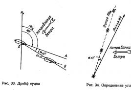
SHIP DRIFT. In drift navigation ( "a") is called the drift of the vessel from the course line under the combined action of the wind and the waves caused by it. When drifting, the ship moves relative to the water under the combined action of the ship's machinery and wind. The line of its actual movement (OV), called the line of the ship's track during drift, does not coincide with the course of the ship (OA). (See Figure 33). When the track is shifted to the right from DP vessel (wind blowing to port) a a plus sign (+) is attributed, and when shifted to the left (the wind blows to starboard), a minus sign (-) is assigned. The relationship between the track angle taking into account the drift ( PUa), IR And a:
PUa \u003d IR + a; IR \u003d PUa - a; a = PUa - IR

The drift angle can be determined by comparing the actual path of the ship obtained from the observations with IR. When following in sight of the coast, a number of reliable navigational observations are made. By connecting the observed points, they get the line of the actual movement of the vessel, i.e., the track line when drifting PUa(Fig. 34). The angle between the track line and the line drawn on the map IR corresponds to the drift angle. The found drift angle with its sign is taken into account in the further calculation. If there is a current in the navigation area, then the resulting drift angle will be the result of the impact on the ship not only of the wind, but also of the current.
ACCOUNTING FOR DRIFT IN CALCULATION. If the ship is drifting, then when plotting, the line of the ship's track during the drift is plotted on the map. They write on it QC, compass correction and drift angle taken into account a with your sign. The distance traveled along the lag is plotted along the path line Sl. It is believed that at a
Sl \u003d Cl (ol2 - ol1); (Where ol2- countdown of the lag at the location of the vessel, ol1- countdown of the lag at the starting point, cl- lag factor).
If the navigator is not sure of the accuracy of the drift angle, then in order to control the safety of navigation, in addition to the track line during drift, it is recommended to draw a line on the map IR. Both of these lines must be clear of underwater obstacles. The calculation is carried out only along the track line, along which the vessel moves.
SEA CURRENTS. Sea currents are the horizontal movements of large masses of water. The flow is characterized by its elements: direction and speed. Current direction ct indicate in degrees in a circular count or rhumbs and are set according to the point on the horizon to which the current is directed. Current speed Vt measured in knots, and its small speeds - in miles per day. According to the nature of the flow, they are classified into constants, the elements of which almost do not change from year to year, periodic, the elements of which change according to a certain law, and temporary (random), the elements of which can change dramatically. In practice, the navigator most often has to deal with constant and periodic (tidal) currents. Information about the elements of permanent and tidal currents is placed in sailing directions, atlases of currents and on maps. At the same time, the average values of the flow elements are indicated, which can differ significantly from the actual ones. The movement of the vessel relative to the ground when swimming in the current is determined by the following factors (Fig. 36).

Under the action of ship engines, the ship moves relative to the water in the direction of its DP, i.e., the lines of the true course of OA. The ship's speed through the water is the speed Vl shown by the lag. At the same time, together with the entire mass of water, the vessel is carried away relative to the ground in the direction of the flow of the OD with the speed of the flow Vt. As a result, relative to the ground, the ship moves along the resultant OB at a speed called the true speed of the ship V. Wherein DP vessel remains parallel to the line IR. The line OB, along which the ship moves under the combined action of the ship's machinery and the current, is called the line of the ship's track on the current. The position of the track relative to the true meridian is determined by the angle NOB, which is called the course angle on the current. PU. Corner "" , enclosed between the line of the true course of the ship OA and the track line OB, is called the drift angle. When the vessel is demolished to the right of its DP(the current is directed to the left side) the "+" sign is assigned, and when drifting to the left, the "-" sign is assigned. Dependence between ( PU), IR And :
PU \u003d IR +; IR \u003d PU -; = PU - IR
NUMBER WHEN FLOATING ON THE CURRENT. When sailing in a constant current, the ship's path line is plotted on the map, along which it actually moves relative to the ground. Above the path line is inscribed QC, compass correction and drift angle with its own sign. For auxiliary calculations, a line is also drawn with a thin line IR, along which distances are plotted Sl, passed by the ship relative to the water according to the indications of the log. Points received on the line IR, are transferred in the direction of the flow to the track line (Fig. 37). Countable points on the track line are marked with time and lag readings, and at the corresponding points on the course line - only lag readings. Points of traverse, opening and hiding of landmarks are applied to the path line (Fig. 38).


CALCULATION WITH JOINT ACCOUNTING FOR DRIFT AND CURRENT. Let us consider the case when the ship moves relative to the ground under the combined action of ship engines, wind and current. To maintain the reckoning on the map, lay the line of the ship's path during the drift and current and inscribe QC, compass correction and total drift angle
c = a + .
In addition, for auxiliary calculations, a drift track is also laid on the map, along which the vessel’s sailing along the log is postponed. Sl. Each point on the drift track corresponds to a point on the line of the actual movement of the ship. These points are interconnected by the flow vector. Graphically, tasks related to finding the track line on the map during drift and current, true speed V and total drift angle With according to given QC, Vl, a, and elements of the flow, drawing a numbered place, precalculating time and ol at the time of arrival at a given point, finding a traverse of the landmark, they decide in the same way as when swimming in the current, but all auxiliary constructions are made on the track line when drifting, replacing the line IR.
ESTIMATES OF THE ACCURACY OF THE NUMBER. As a result of the effect of unaccounted errors, the actual path of the vessel and the distance traveled by it (voyage) will not correspond to those taken into account when calculating on the map, and the actual position of the vessel will not correspond to the calculated one. For an approximate judgment about the errors in the calculation, you can use the following data, which reflect the accumulated generalized experience of navigation and the studies carried out. The duration of the voyage (hours) corresponds to the radial root mean square error, % from S:
Up to 3 hours - 10%; 3-6 hours - 9%; 6-10h - 8%; 10-14h - 7%; 14-18h - 6%; 18-23h - 5%; 23-25h - 4%; more than 35 hours - 3%.
When laying the ship's route on the chart at a certain distance from navigational hazards, it is necessary to take into account the possibility of the ship's deviation from the route line, and the deviation value will increase with increasing distance traveled, especially when sailing with drift and current. The insufficient accuracy of the reckoning necessitates additional control over the position of the vessel, i.e., determining its location not only by reckoning, but also by observations: navigational, astronomical or using GPS.
§ 26. Graphic and written calculation of the ship's route
General information. Laying, performed without checking the position of the vessel by determining its place on coastal objects or on celestial bodies, is called ship's reckoning. The calculation performed on the map by the method of graphic constructions is called graphic dead reckoning of the ship's path, and performed using calculations using special formulas - written(analytical).Graphic reckoning. The essence of this method is as follows. At the moment of determining the starting point a "(see Fig. 29), they notice the time but the ship's clock (up to 1 minute) and the lag counter readings (up to 0.1 miles). The starting point a" is circled and an inscription is made near it in a free place as a fraction: numerator - time, denominator - lag readings 18.00 / 2.5 If the observed point a "is close enough to the starting point a, then from point a" a first course line is drawn in the form of a straight line parallel to the line ac. After that, the line ac is erased from the map, and on the newly drawn line the number of degrees of the compass course is inscribed and next, in brackets, the general correction of the AK compass calculated for this course, so that it can always be established which course was ruled.
If the observed point a" is so far from point a that the ship's track passes close to the dangers (dotted line in Fig. 29), then a new course is laid as shown above in § 25.
On the line of the way, the numbered places of the vessel are hourly marked. To do this, the distance traveled by the ship in 1 hour, on a map scale, is plotted by the meter on the ship's path from the starting point. In the place marked by the meter, a notch is made in the form of a short straight line perpendicular to the track line, as well as an inscription of the time and lag readings.
If the ship needs to change the direction of movement, then at the time of the change of course, the time and the countdown of the lag are again noticed. Having calculated the voyage completed from the last countable point, lay it down along the path, mark the turning point with a record in the form of a fraction (04.37 / 70.2) and plot a new course from this point. If for some reason the vessel ends up at point c", which is significantly far from the point c marked by the preliminary laying, then a new course is laid so as to reach point d of the second turn. After that, the cd line is also erased from the map, and on the line c "d" inscribe the number of degrees KK and next, in brackets, the general correction of the AK compass for THIS course.
Maintaining a graphic laying allows the navigator to have a visual representation of the position of the vessel in relation to navigational hazards.
The accuracy of plotting depends on how correctly the course is plotted and the distance traveled is taken into account. The gasket accuracy is expressed by the following formula:
where Slo - the value of the navigation made by the vessel;
Ek is the error in the total compass correction;
Es - error in lag correction, %.
Example 26. Determine the radius of the circle within which should be the position of the ship that has passed one course of 60 miles, if the possible error in the course is ±1°, and the possible error in the lag correction is (-2.0%).
Solution. By formula (31)
Turning the vessel from one course to another introduces some additional error into the laying, since after changing the rudder, the vessel does not instantly change the direction of movement, but describes a certain curve (circulation) by the center of gravity.
Accounting for circulation is of great importance when navigating in cramped waters, narrow spaces, skerries, etc. Circulation is taken into account as follows.
The ship (Fig. 30), following in the direction of K1, at point A must turn in the direction of K2 (the angle of rotation is a). To take into account the circulation, a bisector of the internal angle of rotation is drawn (3 = 180 ° -a and on it they look for the center O of the circle with a radius equal to half the tactical diameter of the circulation Dc which is determined empirically and usually expressed in the lengths of the ship's hull.
After drawing a circle, mark the points B and C of its touch with the lines K1 and K2. Point B is considered the beginning of the turn.
Written reckoning. The reckoning position of the vessel can be obtained by the analytical method of written reckoning in those cases when it is irrational to use the graphic reckoning of the vessel's path: when sailing in high latitudes, during ice navigation, whaling, etc.

Rice. thirty.
The essence of written reckoning is to determine the coordinates of the point of arrival with known coordinates of the point of departure, the course and navigation of the ship. With the help of written reckoning, it is possible to solve the inverse problem: to determine the navigation and course of the vessel from the known coordinates of the points of arrival and departure.
Based on formulas (4) and (5), the coordinates of the point of arrival can be expressed as follows:

If navigation takes place at low latitudes, then the expressions for RH and RH can be easily obtained from consideration of the so-called navigation triangle ABC (Fig. 31), in which:
A - departure point with coordinates cp1 and L2;
B - point of arrival with coordinates cp2 and L2;
K \u003d LSAB - ship's heading when moving from point A to point B;
AB=S - distance between departure and arrival points;
AC=RSh and VS=OTSH.
If we assume that the triangle ABC is flat and rectangular, then directly from Fig. 31 we get:

Further, substituting the value of OT W from formula (6), we obtain
In fact, AABC is not flat and not rectangular (the figure ACBC "is a spherical trapezoid). Therefore, RD1 \u003d \u003d RD2 (cpB \u003d cpA), but the real value
Where
![]()
- average latitude.
To facilitate the work of the navigator in the MT-63 there are auxiliary tables: tab. 24 gives the RSH and RSH values for the S (swimming) and K (heading) arguments; tab.
25-a - RD values in terms of φm and RNR.

Rice. 31.
If the reckoning is carried out on the transition made by the ship on the same course, then it is called simple, and if there are several courses, it is called composite. Composite reckoning is used when sailing on the current, especially on the tide; in this case, the course is taken into account as a separate additional course (courses). In composite calculation, RSH and RD are calculated or selected from tables for each individual course and swimming. Composing the algebraic sum of all RSH and OSH, we get the general RSH and the general OSH. Next, calculate the latitude of the point of arrival using the formula
φ2 = φ1 + general PSH
And the general formula
When sailing, the ship is on the border of two environments - air and water, the movement of which affects it, deviating from the course and changing the speed of movement.
The drift of a ship by the wind is called drift. Wind is the forward movement of air masses. Wind direction is the direction (in degrees) from where the wind is blowing. Wind speed is measured in meters per second or in points.
Fig.1
Let V0 be the speed of the ship relative to the water, due to the work of its own propellers (Fig. 1). The air resistance to the movement of the ship is perceived by the observer on the ship as a counter flow of air, the velocity vector of which is (-V0). Let u be the true wind speed vector. The counter flow of air and the true wind, adding up, form a total flow observed on a moving ship and called the apparent (observed) wind. The apparent wind speed vector is equal to the geometric sum:
W \u003d u + (-V0) \u003d u - V0.
The apparent wind speed is determined automatically using an anemorumbometer or manually using an anemometer, the direction KW is determined by an anemorumbometer or in the direction of a flag or pennant. Seeming wind. Inactive on the ship at a heading angle qW, it causes the total aerodynamic force P applied to the center of the ship's windage. Due to the refractive properties of the superstructure, the direction of the force P in the general case does not coincide with the direction of the apparent wind. Under the action of the force P, the ship is displaced in the direction of this force with a drift velocity VDR.
Let us decompose the velocity VDR into components VDR X along the diametrical plane and VDR Y along the traverse. The speed VDR X, depending on the direction of the apparent wind, is subtracted or added to the speed V0. If the lag works, it takes this speed into account. That's why
Vl \u003d V0 + VDR X.
VDR Y speed deviates the ship from the set course. Having geometrically added the speed of the ship Vl with the speed VDR Y, we get the vector V of the actual, or ground, speed of the ship:
V \u003d Vl + VDR Y.
As you can see, when adding the velocities Vl and VDR Y, the ship moves in the direction of their resultant.
The line along which the ship actually moves relative to the seabed under the action of propulsors and the apparent wind is called the drift track. The diametrical plane of the ship, when moving along the track line, remains parallel to the line of the true course. This is due to the fact that the helmsman constantly maintains a given true course. Consequently, the ship moves along the path forward not with its bow, but with its cheekbone.
The angle in the plane of the true horizon between the northern part of the true meridian and the track line during drift is called the track angle during drift PU?.
The angle in the plane of the true horizon between the lines of the true course and the track when drifting is called the drift angle?. If the wind is blowing to the port side of the ship, the drift angle is positive (the course angle during drift is greater than the true heading). With wind from the starboard side, the drift angle is negative (the course angle during drift is less than the true heading).
The drift angle depends on the speed and heading angle of the apparent wind, on the speed and design features of the ship: the height and architecture of the superstructures, the surface part of the hull and the shape of the hull contours. The drift angle is measured with a driftmeter. In the absence of this instrument, drift angles for various navigation conditions are selected from a drift table compiled from experimental data. From fig. 1 is visible:
Formulas - algebraic, angle? is taken with its sign.
In the practice of ship navigation, it is necessary to solve mainly two problems related to the drift of the ship. Direct task:
Calculate the ground angle when the launcher drifts? (track of the ship when drifting), if the true heading is set.
To solve this problem, you need:
- determine the sign of the drift angle?;
— calculate the heading angle qW of the apparent wind;
— choose the angle value? from the drift table by arguments: by ship speed and qW;
- calculate the track angle during the drift of the launcher ?, lay the track on the map.
KK = 79.0°; Vl = 12.0 knots;
?GK = + 1.0°; wind 5° -12 m/s.
Solution:
The wind is blowing to the port side of the ship - angle? positive:
IR = KK + ?GK = 80.0°;
? = +4.0°; PU? = IR + ? = 84.0°.
2. Laying true radio bearings in case the radio beacon is located outside the eastern or western borders of the map frame.
To find the position of the defining point (point M ') through which the radio bearing will be drawn on the KRMK (point A), it is necessary:
1) ? from "RTSNO" write out the coordinates of KRMKA (? A,? A);
2) ? calculate value? ? = ?Р – ?А, where? Р – longitude of the side frame of the map;
3) ? draw a parallel of KRMKA on the map (? A - from "RTSNO") and set aside the segment;
4) ? through t. A "to draw an additional meridian aa;
5) ? from t. A’ hold Lok. P KRMKA A to the intersection with aa - t. M;
6) ? from t. M along aa, set aside a segment and through the obtained point M 'to draw a radio bearing on KRMK A? this will be the desired line of position (I–I).
Determining the ship's position by calculating its current (countable) coordinates from the known initial ones along the course, speed, taking into account drift, drift and time is called the calculation of the ship's coordinates ( dead reckoning ) or abbreviatedreckoning .
The coordinates of the calculated place of the ship are called countable coordinates and are marked:
φ WITH - reckoning latitude;
λ WITH - countable longitude.
Countable place - the position of the ship, determined on the basis of the reckoning of the coordinates of its position.
Assignment of reckoning is the orientation of the vessel relative to the terrain with an accuracy that ensures the navigational safety of its navigation.
The line along which the ship actually moves under the influence of propulsion, wind and current is called track line.
Essence of numbering consists in the fact that from a known starting place on the navigation chart, the directions of the vessel's movement and the distances traveled along them are plotted in order to obtain its position at any given point in time.
reckoning vessel coordinates classified:
By counting method :
graphic , based on the continuous accounting of the elements of the numeral and their representation on the navigation map;
analytical , based on the calculation of the current coordinates according to certain mathematical dependencies.
By degree of automation :
automatic produced with the help of special computers (autoplotter, autonumerator, etc.);
observational , automatic reckoning based on continuous updating of the current reckonable coordinates by external landmarks;
manual , produced with the help of graph-analytical actions performed manually or using tables.
Dead reckoning requirements
To the reckoning the following requirements:
calculation should be continuously, in order to know the position of the ship (its current coordinates) relative to the terrain at any time;
reckoning should be accurate to ensure navigational safety of navigation and the solution of problems inherent in this vessel;
reckoning should be enough simple and visual.
The preferred way to account for ship movement is automatic with mandatory manual graphic reckoning, which, in essence, satisfies all the requirements for reckoning.
Even in the presence of modern navigation systems, in which the reckoning process is fully automated and has high accuracy, manual graphic reckoning is mandatory to control and eliminate misses in the event of malfunctions in the instruments.
The manual graphic method of reckoning is often called a navigation pad, although the latter → the concept is wider (+ determining places, etc.).
Navigation laying of the ship's path – graphic constructions on the sea chart when solving navigation problems of navigation.
Tasks to be solved with manual graphical dead reckoning
In the absence of wind and current, the ship moves relative to the seabed only under the influence of its own propulsion.
If we neglect the yaw of the vessel (deviations of the helmsman from the course set for it) and consider the correction of the heading indicator to be constant, then the line of the vessel's track on the navigation chart will be displayed as a straight line coinciding with the direction of the true course.
Vessel path - the direction of movement of the ship's center of mass, measured by the horizontal angle between the northern part of the true meridian and the ship's track line in a clockwise direction from 0° to 360° (circular counting system).
Vessel track - the line along which the ship's center of mass moves relative to the seabed(fig.5.3).
Rice. 5.3. Track line and ship track
With manual graphical reckoning of the ship's coordinates, without taking into account drift and current, the following tasks are solved:
calculation and laying of true courses;
calculation and laying of the distances covered by the vessel;
accounting for circulation - changes in the course of the vessel.
When conducting the reckoning, the readings of the instruments are used:
repeater course indicator(magnetic compass, gyrocompass, etc.) – QC;
repeater lag(values V L And OL);
tachometers(N rpm - the number of revolutions of the propellers);
ship's clock (current time).
The position of the ship at anchor (barrel, at the berth), determined by observations of coastal landmarks or by dead reckoning (Fig. 5.4), is taken as the starting point for the beginning of the dead reckoning.

Rice. 5.4. Registration of graphic reckoning of the ship's route on the route map
1. By countable coordinates ( φ WITH , λ WITH) we put the anchorage place, near which in the free place we record the time of shooting from anchor and the full reading of the lag counter ( OL 0 ):
In all cases, the fractional bar of the entry is carried out along a ruler and parallel to a parallel.
2. From the anchorage point, we draw the direction of the true course line, calculated by the formula:
If the heading comes from a gyrocompass, then
If the heading comes from a magnetic compass, then
|
IR = QC MK + Δ MK |
|
Δ MK = d + δ |
– correction of the magnetic compass.
Above the anchorage point true course line (track line) the inscription is made:
QC is the abbreviation for the compass course ( GKK, KK GL , KK P);
127.0 ° - the value of the compass course given to the helmsman (equal sign between QC and 127.0 ° is not set according to the rules);
(+2.0°) – the value and sign of the adopted heading indicator correction are indicated in brackets.
The inscription above the course line allows you to control :
Correctness of keeping the set course (127.0°) by the helmsman;
The value of the accepted and taken into account correction of the heading indicator (+2.0 °);
The correctness of the direction of the line of the true course on the map (129.0 °).
When the ship follows a given course, the helmsman regularly (every 15 minutes) checks the readings of the courses against the main course indicator (according to GC or by GA or others) and using a magnetic compass with a report to the captain of the watch (the watch officer).
The countable coordinates of the ship are recorded in the ship's log :
when shooting a vessel from anchor (barrel) and when anchoring (barrel);
when sailing by dead reckoning, at hours multiple of the 4th (00, 04, 08 ... 20);
every hour when the ship is sailing by dead reckoning near the shore;
when changing the navigation (navigation) watch and in other cases as directed by the captain.
The numerable position of the ship is applied on the navigation chart :
in hours divisible by four (00, 04 ... 20);
when the vessel changes its course or speed;
when changing the navigational (running) watch;
every hour when the ship is sailing near the shore or in constrained waters, and in other cases, as directed by the captain.
To find a reckonable place for a given (current) time, follow (Fig. 5.4):
Record ship's clock readings to within ± 1 minute (11.00) ;
Fix lag count ( OL 1 ) accurate to 0.1 mile (60,4) ;
(For V L= 18 knots → TO L = 1,02)S L= 1.02 11.8 = 12,0 miles.
S ABOUT =12,0 miles
provided that S L =S ABOUT → set aside its value (on a map scale) from the starting point along the true course line and plot the calculated position of the vessel (at 11.00) with a symbol ( stroke line IR ~ 5 mm).
Next to the place to be counted, write as a fraction ![]()
When conducting reckoning, it often becomes necessary know the time and countdown of the lag of the ship's arrival at a given point(meeting point, anchorage point, etc.).
Such a point can be set (fig.5.5):

Rice. 5.5. Ways to set a point on the map
coordinates ( φ, λ );
direction to the landmark ( IP or KU);
distance ( D) to the landmark, etc.
The procedure for solving the problem .
 GRAPHIC CALCULATION OF THE WAY OF THE SHIP. In order to judge the safety of navigation, navigate the environment and choose the right courses for further movement, the navigator must at any time know the position of his vessel. To do this, he maintains a navigation pad. Before the ship goes on a voyage, under the guidance of the captain, they study the navigation conditions for the entire upcoming passage using maps and navigational aids. Based on these data, preliminary laying is performed. However, it only gives a general idea of the transition conditions. From the moment you embark on a voyage, the final choice of courses and all factors taken into account are determined by the specific sailing situation. Therefore, the flight is carried out by the executive laying. It includes dead reckoning, calculations and charting, maneuvering calculations to avoid other ships.
 Dead reckoning is the continuous accounting of the elements of the vessel's movement (speed and direction) and the effects of external forces in order to determine the coordinates of the vessel (countable place) without observing coastal landmarks and celestial bodies (observations). This accounting is carried out on the basis of the values of the course, speed and drift vector of the vessel. The starting point for dead reckoning on the map is determined by the captain. For such a point, the exact position of the vessel, obtained immediately after leaving the port water area, a floating lighthouse, a receiving buoy, etc., can be taken. Its coordinates are recorded in the ship's log. By the time the executive laying begins, you should turn on the log, determine the compass correction by alignment or in another way.
 KEEPING NUMBER WHEN SWIMMING WITHOUT DRIFT AND CURRENT. When sailing without drift and current, the ship's path on the map coincides with the IC line, therefore, the ship's movement on the map is taken into account along the IC lines, along which the distances traveled by the ship along the log are plotted, taking into account its coefficient Kl. From the starting point on the map, a line of the first course is laid. The IC taken from the card is transferred to the CC, on which they are placed according to the magnetic compass. On the map above the IR line, the compass course and its correction are inscribed. The distance Sl traveled along the course is determined by the lag: Sl = Cl (ol 2 - ol 1); (Where ol 2 is the lag reading at the vessel's location, ol 1 is the lag reading at the starting point, Kl is the lag coefficient).
 On the lines of the IC, in the cases indicated below, the reckoning of the ship's revenge is applied, i.e., the place calculated according to the course and navigation. If navigation is performed near the coast, countable points are marked every hour, in the open sea - at the end of the watch. In addition, a reckonable place is applied at the points of the beginning and end of turns, when changing speed, when receiving observations. Near the ship's position, in the form of a fraction, the moment is recorded according to the ship's clock with an accuracy of 1 min (T) and the lag reading with an accuracy of 0.1 miles (ol). (See Figure 31).

 In real conditions of sea navigation, three main options are possible, which determine the appropriate practical methods of dead reckoning of the yacht's way: sailing in conditions of a stable full wind; sailing in conditions of stable opposite wind; sailing in winds that are unstable in strength and direction.
 In the first case, the yacht is usually driven along the line of the path laid during the preliminary laying. The terms of calculation are favorable here. In the second case, tacking is performed relative to the general course, while the actual path laid on each tack does not coincide with the preliminary laying. If the tack is not too steep, then the helmsman accurately maintains a given course, which simplifies the reckoning and increases its accuracy. Under such conditions, the duration of the tacks depends on the angle of the tack (the angle between the general course and the path of the yacht). If the angles of the right and left tacks are equal, their duration is the same, and the tacking can be symmetrical. If not, dead reckoning and laying the track are performed on each private tack according to the instrument data. If there is no lag, it is recommended to evaluate the speed on each tack.
 When tacking, it may happen that the helmsman, at the direction of the captain of the yacht, when getting out into the wind, does not pay attention to the compass. Here, at small but equal time intervals (15 - 30 minutes), the average QC and the corresponding IC are determined and recorded, according to which the data obtained by the lag or speed are put aside. In unstable winds, the helmsman does not set the course, but sets the task of guiding the sail in search of the wind, adhering as close as possible to the general course. Sometimes in such a situation, depending on local indications and the weather forecast, it may be beneficial to deviate from the general course in order to get a full steady wind sooner (for example, a breeze offshore). In all these cases, in the interests of dead reckoning, all turns are recorded on the yacht and on each tack (at the beginning and end of the tack, it is obligatory) with a certain frequency (1-2 times per hour, depending on conditions), data on the movement of the vessel (time, course , speed, lag reading). These records are processed by averaging the course and speed of each tack, and then plotted on the chart.
 Practice shows that the accuracy of the calculation in such conditions increases with increasing discreteness of observations. Approximation errors of curved sections of navigation by straight lines will be insignificant compared to other errors.
 SHIP DRIFT. In navigation, drift ("a") refers to the drift of a vessel from the course line under the combined action of the wind and the waves caused by it. When drifting, the ship moves relative to the water under the combined action of the ship's machinery and wind. The line of its actual movement (OV), called the line of the ship's track during drift, does not coincide with the course of the ship (OA). (See Figure 33). When the track line is shifted to the right of the ship's DP (the wind blows to the port side), a plus sign (+) is assigned to a, and when the track is shifted to the left (the wind blows to the starboard side), a minus sign (-) is assigned. Relationship between track angle with drift (PUa), IC and a: PUa = IC + a ; IR \u003d PUa - a; a = PUa - IR

 The drift angle can be determined by comparing the actual path of the vessel obtained from the observations with the IR. When following in sight of the coast, a number of reliable navigational observations are made. By connecting the observed points, we get the line of the actual movement of the vessel, i.e., the track line during the drift of the launcher (Fig. 34). The angle between the track line and the IR line plotted on the map corresponds to the drift angle. The found drift angle with its sign is taken into account in the further calculation. If there is a current in the navigation area, then the resulting drift angle will be the result of the impact on the ship not only of the wind, but also of the current.
 ACCOUNTING FOR DRIFT IN CALCULATION. If the ship is drifting, then during the laying, the line of the ship's track during the drift is plotted on the map. It is inscribed with KK, the compass correction and the drift angle a taken into account with its sign. Along the path line, the distances Sl traveled along the lag are laid off. It is believed that for a
 If the navigator is not sure of the accuracy of the drift angle, then in order to control the safety of navigation, in addition to the drift track, it is recommended to plot the IR line on the map. Both of these lines must be clear of underwater obstacles. The calculation is carried out only along the track line, along which the vessel moves.
 SEA CURRENTS. Sea currents are the horizontal movements of large masses of water. The flow is characterized by its elements: direction and speed. The direction of the current Kt is indicated in degrees in a circular count or rhumbs and is set according to the point on the horizon to which the current is directed. The current velocity Vt is measured in knots, and its small speeds are measured in miles per day. According to the nature of the flow, they are classified into constants, the elements of which almost do not change from year to year, periodic, the elements of which change according to a certain law, and temporary (random), the elements of which can change dramatically. In practice, the navigator most often has to deal with constant and periodic (tidal) currents. Information about the elements of constant and tidal currents is placed in sailing directions, atlases of currents and on maps. At the same time, the average values of the flow elements are indicated, which can differ significantly from the actual ones. The movement of the vessel relative to the ground when swimming in the current is determined by the following factors (Fig. 36).

 Under the action of ship engines, the ship moves relative to the water in the direction of its DP, i.e., the line of the true course OA. The speed of the ship in relation to the water is the speed Vl indicated by the log. At the same time, together with the entire mass of water, the ship is carried away relative to the ground in the direction of the flow of the OD with the speed of the flow Vt. As a result, relative to the ground, the ship moves along the resultant OB at a speed called the true speed of the ship V. In this case, the ship's DP remains parallel to the IR line. The line OB, along which the ship moves under the combined action of the ship's machinery and the current, is called the line of the ship's track on the current. The position of the track line relative to the true meridian is determined by the angle NOB, which is called the track angle on the PU current. The angle " " between the ship's true heading OA and the track OB is called the drift angle. When the vessel is drifting to the right of its DP (the current is directed to the port side), a "+" sign is attributed, and when drifting to the left, a "-" sign is assigned. Relationship between (PU), IR and:
 PU \u003d IR +; IR \u003d PU -; = PU - IR
 NUMBER WHEN FLOATING ON THE CURRENT. When sailing in a constant current, the ship's path line is plotted on the map, along which it actually moves relative to the ground. Above the track line, they inscribe KK, the compass correction and the drift angle with their own sign. For auxiliary calculations, an IR line is also applied with a thin line, along which the distances Sl are plotted, passed by the ship relative to the water according to the lag readings. The points obtained on the IC line are transferred in the direction of the current to the track line (Fig. 37). Countable points on the track line are marked with time and lag readings, and at the corresponding points on the course line - only lag readings. Points of traverse, opening and hiding of landmarks are applied to the path line (Fig. 38).

 CALCULATION WITH JOINT ACCOUNTING FOR DRIFT AND CURRENT. Let us consider the case when the ship moves relative to the ground under the combined action of ship engines, wind and current. To maintain the reckoning on the map, lay the line of the ship's path during drift and current and inscribe KK, the compass correction and the total drift angle c \u003d a +.
 In addition, for auxiliary calculations, a drift track is also laid on the map, along which the vessel’s navigation along the Sl log is postponed. Each point on the drift track corresponds to a point on the line of the actual movement of the vessel. These points are interconnected by the flow vector. Graphically, tasks related to finding the track line on the map during drift and current, the true speed V and the total drift angle c for the given KK, Vl, a, and flow elements, plotting a countable place, precalculating time and ol at the time of arrival at a given point, finding a traverse of the reference point is solved in the same way as when swimming in the current, but all auxiliary constructions are made on the track line during drift, replacing the IR line.
 ESTIMATES OF THE ACCURACY OF THE NUMBER. As a result of the effect of unaccounted errors, the actual path of the vessel and the distance traveled by it (voyage) will not correspond to those taken into account when calculating on the map, and the actual position of the vessel will not correspond to the calculated one. For an approximate judgment about the errors in the calculation, you can use the following data, which reflect the accumulated generalized experience of navigation and the studies carried out. Duration of navigation (hours) corresponds to the radial root mean square error, % of S: Up to 3 hours - 10%; 3-6 hours - 9%; 6-10 hours - 8%; 10 -14 h - 7%; 14-18 hours - 6%; 18-23 h - 5%; 23-25 h - 4%; more than 35 hours - 3%. When laying the ship's route on the chart at a certain distance from navigational hazards, it is necessary to take into account the possibility of the ship's deviation from the route line, and the deviation value will increase with increasing distance traveled, especially when sailing with drift and current. The insufficient accuracy of the reckoning necessitates additional control over the position of the vessel, i.e., determining its location not only by reckoning, but also by observations: navigational, astronomical or using GPS.